Introduction
Inertial measurement units are one of the most common sensors in navigation. It contains an accelerometer and gyroscope, and sometimes a magnetometer and barometer. The accelerometer is responsible for the acceleration measurement, while the gyroscope is responsible for the angular velocity measurement. Each of these measurements is expressed along the three-axis coordinate system x,y,z. An inertial measurement unit is a device that measures three-axis attitude (or angular velocity) and acceleration. To increase reliability, it is also possible to equip each axis with more sensors. Generally, the IMU should be installed at the center of gravity of the object being measured.

IMUs are commonly used to control modern vehicles, including missiles, robots, submarines, aircraft (attitude and heading reference systems), including unmanned aerial vehicles (UAVs), etc., and spacecraft, including satellites and landers. Developments in recent years have allowed the production of IMU-enabled GPS devices. The IMU allows the GPS receiver to operate when the GPS signal is unavailable, such as in tunnels, inside buildings, or when there is electronic interference.
Operating principle
An inertial measurement unit (IMU) works by detecting linear acceleration using one or more accelerometers and measuring angular velocity using one or more gyroscopes. Some also include magnetometers. Pitch, roll and yaw are commonly used as attitude reference systems.
Instructions
The IMU is often integrated into an inertial navigation system, which uses raw IMU measurements to calculate the attitude of the drone. A simpler version of the INS, called an Attitude and Heading Reference System (AHRS), uses an IMU to calculate the vehicle's heading attitude relative to magnetic north. Data collected from the IMU sensors allows computers to track the aircraft's position using a method called dead reckoning.
In land vehicles, IMUs can be integrated into GPS-based car navigation systems or vehicle tracking systems, giving the system dead reckoning capabilities and the ability to collect as much information as possible about the vehicle's current speed, turn rate, heading, inclination and acceleration. The accurate data with the vehicle's wheel speed sensor output as well as the reverse gear signal (if available) are used for better purpose traffic collision analysis.
In addition to navigation purposes, IMUs are used as orientation sensors in many consumer products. Almost all smartphones and tablets contain an IMU as an orientation sensor. Fitness trackers and other wearable devices may also contain IMUs to measure movement, such as running. The IMU is also able to determine an individual's developmental level while exercising by identifying the specificity and sensitivity of specific parameters related to running. Some gaming systems use IMUs to measure motion. Low-cost IMUs have fueled a boom in the consumer drone industry. They are also frequently used in sports technology (technical training) and animation applications. They are competing technologies for motion capture technology.
In a navigation system, data reported by the IMU is fed into a processor that calculates altitude, speed, and position. A typical implementation called a strapdown inertial system integrates the angular rate of a gyroscope to calculate angular position. It is fused with the gravity vector measured by the accelerometer in a Kalman filter to estimate the attitude. Attitude estimation is used to convert acceleration measurements into an inertial reference frame (hence the name inertial navigation), where they are integrated once to obtain linear velocity and twice to obtain linear position.
For example, if an IMU installed in an aircraft moving along a certain direction vector will measure the aircraft's acceleration as 5 m/s2 for 1 second, after 1 second the guidance computer will infer that the aircraft must be flying at 5 m/s, and Must be 2.5 m from the initial position (such as a satellite or terrestrial radio transponder, although external sources are still used to correct for drift errors, and since the position inertial navigation system allows the update frequency to be higher than the smoothness of the vehicle motion can be perceived on the map display This method of navigation is used in conjunction with a system called GPS (because the navigation system position output is often used as a reference point to produce a moving map), the guidance system can use this method to show the pilot the aircraft's geographical position at a certain moment in time. Like a moving map display.
A major disadvantage of using IMUs for navigation is that they are often affected by accumulated errors. Because the guidance system continuously integrates acceleration versus time to calculate velocity and position, any measurement error, no matter how small, accumulates over time. This results in "drift": a growing discrepancy between where the system thinks it is and where it actually is. Due to integration, a constant error in acceleration results in a linear error growth in velocity and a quadratic error growth in position. A constant error in the attitude rate (gyro) results in a quadratic error growth in velocity and a cubic error growth in position.
IMU performance
There are many types of IMUs, depending on the application type, with performance ranges:
Gyroscope from 0.1°/s to 0.001°/h (angular velocity random walk)
Accelerometers from 100 mg to 10 µg (bias repeatability)
Roughly speaking, this means that for a single uncorrected accelerometer, the cheapest (100 mg) loses its ability to provide 50 meter accuracy after about 10 seconds, while the best accelerometer (10 mg) Lost the ability to provide 50 meter accuracy. µg) loses accuracy over 50 meters after approximately 17 minutes.
The accuracy of the inertial sensors within the inertial measurement unit (IMU) has a more complex impact on the performance of the inertial navigation system (INS).
The behavior of gyroscope and accelerometer sensors is usually represented by errors based on the following, assuming they have appropriate measurement range and bandwidth:
1.Offset error: This error can be divided into stability performance (the drift of the sensor under constant conditions) and repeatability (the error between two measurements under similar conditions, but with different intermediate conditions).
2.Scale factor error: First-order sensitivity error due to non-repeatability and nonlinearity.
3.Misalignment error: due to imperfect mechanical installation.
4.Noise: Depends on required dynamic performance.
5.Environmental sensitivity: mainly sensitivity to thermal gradients and acceleration.
All of these errors depend on various physical phenomena unique to each sensor technology. Depending on the target application and to be able to make the right sensor selection, it is important to consider the needs in terms of short- and long-term stability, repeatability, and environmental sensitivity (mainly thermal and mechanical environments). In most cases, the target performance of the application is better than the absolute performance of the sensor. However, sensor performance is repeatable over time, with more or less accuracy, so it can be evaluated and compensated to enhance its performance. This real-time performance enhancement is based on sensor and IMU models. The complexity of these models will then be chosen based on the performance required and the type of application being considered. The sensor and IMU models are calculated at the factory through a dedicated calibration sequence using a multi-axis turntable and a climate chamber. They can be calculated for each individual product or generally for the entire production. Calibration typically improves a sensor's original performance by at least twenty years.
Assemble
High-performance IMUs or IMUs designed to operate in harsh conditions are often suspended by shock absorbers. These shock absorbers need to master three effects:
1.Reduce sensor errors due to mechanical environmental requirements.
2.Protect sensors as they may be damaged by shock or vibration.
3.Contain spurious IMU motion within a limited bandwidth that processing will be able to compensate for.
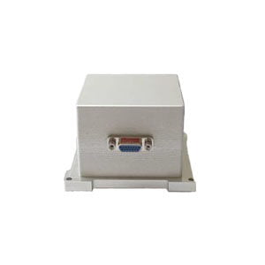
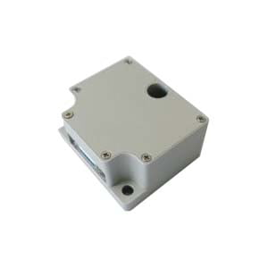
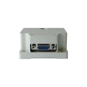
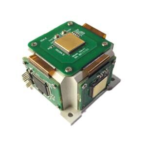
Reducing these errors often prompts IMU designers to increase processing frequencies, and this is made easier with the latest digital technology. However, developing algorithms that can eliminate these errors requires deep inertial knowledge and a close understanding of sensor/IMU design. On the other hand, if suspension has the potential to improve IMU performance, it will have side effects on size and mass. The ER-MIMU01 product developed by Ericco uses a three-axis gyroscope and a three-axis accelerometer. Below are the important parameters of the gyroscope and accelerometer added to the ER-MIMU01 model IMU:
Gyro (ER-MG2-100 (0.02°/hr))
Bias instability:<0.02
Bias stability (1σ 10s): <0.1deg/hr
Bias stability (1σ 1s): <0.3deg/hr
Bias repeatability (1σ): <0.1deg/hr
Accelerometer (range: 2-10g)
Bias Repeatability: 100-300ug
Bias Repeatability: <500ppm
Class II Non-linearity Coefficient: <100ug/g2
Accelerometer (range: 10-30g)
Bias Repeatability: 200-500ug
Bias Repeatability: <500ppm
Class II Non-linearity Coefficient: <100ug/g2
If you are interested in the imu studied by Ericco, please contact us.
More Technical Questions
1.What are the disadvantages and remedies of IMU?
2.What Is The Principle Of The IMU?
5.What is the technology development trend of MEMS IMU?
6.Do You Know The Principle of IMU (inertial measurement unit)?
Products in Article