The electronic compass also known as digital compass, it has been widely used as a navigation instrument or attitude sensor in modern technology. Compared with the traditional pointer type and balance frame structure compass, the electronic compass has low energy consumption, small size, light weight, high precision and miniaturization. Its output signal can be digitally displayed through processing. It can not only be used to point, but also can be directly sent to the autopilot to control the operation of the ship.
The dimensional (3D)electronic compass consists of a three-dimensional reluctance sensor, a biaxial inclination sensor and an MCU. The three dimensional reluctance sensor is used to measure the earth magnetic field. The inclination sensor compensates when the magnetometer is not horizontal. The MCU handles signals from magnetometers and tilt sensors as well as data output and soft and hard iron compensation. The magnetometer uses three mutually perpendicular magnetoresistance sensors, each of which is axial to measure the strength of the geomagnetic field in that direction. The forward direction is called the x-direction sensor to detect the vector value of the geomagnetic field in the x-direction; Right - or Y-oriented sensors detect the vector value of the geomagnetic field in the Y direction; The downward or z-direction sensor detects the vector value of the geomagnetic field in the z-direction. The sensor sensitivity in each direction has been adjusted to an optimal point according to the component vector of the geomagnetic .
The azimuth value can be determined only by the two component vector values of the magnetic field at X and Y:
Azimuth=arcTan(Y/X)
This relation is only valid when the instrument is parallel to the ground surface. When the instrument is tilted, the accuracy of the azimuth value will be greatly affected, and the magnitude of the error depends on the position of the instrument and the size of the tilt angle. To reduce the impact of this error, a biaxial tilt sensor is used to measure the pitch and roll angle. The pitch angle is defined as the change of the angle in the forward and backward direction. The roll angle is an angle change from left to right. The electronic compass converts and calculates the pitch and roll angle data to "pull" the magnetometer's three axial vectors back to the horizontal position in the original position.
The standard conversion calculation is as follows:
Xr = Xcos alpha + Ysin alpha sine beta Zcos beta sine alpha
Yr = Ycos beta + Zsin beta
Here Xr and Yr are the values to be converted to the horizontal position
α is the pitch angle
β is the roll angle
It can be seen from the above three calculation formulas that the Z axis vector plays a very important role in the whole compensation technology. To use these values correctly, the pitch and roll figures must be updated at all times. A ceramic matrix electrolyte sensor with a biaxial wide linear range, high resolution and low temperature drift coefficient is used to measure the pitch angle and roll angle. The value of the angle is compensated by the temperature sensor on the circuit board.
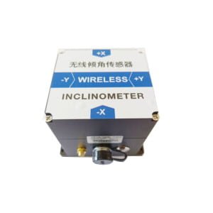
In order to make the electronic compass in other areas of better application, launched low Cost 2D Electronic Compass ER-EC-220 with hard magnetic, soft magnetic and tilt compensation,It is a high-precision two-dimensional electronic compass, which measures the azimuth from 0 to 360°.It is composed of industrial microcontroller with high reliability and strong anti-interference ability, high-precision magnetic sensor drive chips, and integrates hard magnetic interference and soft magnetic interference compensation technology. It can be customized according to customer needs, and it is very convenient to quickly integrate the electronic compass function into various products.The product is small in size and low in power consumption, and can be used in many fields such as antenna stability, automotive, and system integration. Strong shock resistance, can work normally in extremely harsh environments, which is more suitable for today’s miniaturized high-precision measurement.
More Technical Questions
1.Electronic Compass and Gyroscope
2.Do You Know The Difference between electronic compass and GPS navigation?
3.How to Use Electronic Compass in Heading Measurement of Underwater Robot ?
4.Application of Gyroscope in Electronic Compass
5.Do you Know the Common Problems When Using an Electronic Compass?
6.What Is An Electronic Compass?
Products in Article