The quartz flexure accelerometer is widely used in fields such as navigation, guidance, weaponry, and detection. It comprises more than ten components and involves over a hundred manufacturing processes. Its operating environment is complex, and instrument failure may occur due to changes in external conditions or internal faults, thereby affecting navigation and detection accuracy. Severe failures can directly lead to mission failures. Common fault modes include saturation, non-functionality, and abnormal output.
This article mainly introduces the fault manifestations and reasons of quartz flexure accelerometers, and proposes solutions, especially based on the analysis of the working principle of the servo circuit. A method for detecting foreign objects based on electrical excitation is proposed, which can determine the presence of foreign objects without disassembling the core of the instrument. This method can be applied in the production and fault diagnosis processes of accelerometers.
1. Failure mechanism analysis
The working principle of the quartz flexure accelerometer (Figure 1) is that the sensitive mass perceives changes in acceleration, and the induced current is output through the servo circuit. The voltage output is obtained through sampling resistance, and the magnitude of the voltage is proportional to the acceleration. Common fault modes include saturated output (divided into positive saturation and negative saturation), non-functionality (output is zero), and abnormal output.
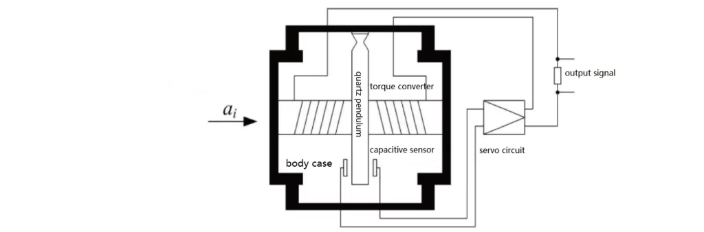
The upper and lower moments of the quartz flexure accelerometer are coated with the pendulum to form the upper and lower capacitance sensors. When the sensitive mass senses the acceleration change, i.e., the capacitance signals detected by the upper and lower capacitance sensors (defined as C+ and C-) are unequal, the capacitance signal will be changed by the two gold wires (defined as C+ and C-) and the gold film on the capacitance beam.
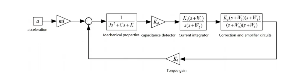
When the capacitance signals detected by the accelerometer are not equal, the capacitance signal is transmitted to the servo circuit through two gold wires (defined as C+ and C- gold wires) and the gold film on the beam, and the capacitance signal is input to the torque converter coil, which generates the feedback torque to pull the pendulum back to the equilibrium position, and the capacitance detector continues to be sensitive to the acceleration signals. The accelerometer servo circuit control principle is shown in Fig.2.
2. Common causes of accelerometer failure
2.1 Foreign Object Faults
Common foreign objects include cured adhesive particles, dust particles, and metal debris. Metal debris, being conductive, often result in short-circuit faults similar to wire shorts. When such debris restricts the movement of the pendulum, bringing it closer to the upper torque motor, according to the structure and working principle of the accelerometer, the capacitance value detected by the upper capacitive sensor consistently exceeds that detected by the lower capacitive sensor.
Based on the closed-loop control principle of the servo circuit, the accelerometer continuously outputs positive current until it reaches the circuit's output capacity, resulting in positive saturation output. Similarly, when the debris brings the pendulum closer to the lower torque motor, the servo circuit continuously outputs increasing negative current, resulting in negative saturation output from the accelerometer.
2.2 C+/C- Open Circuit
The wire diameter inside the quartz flexure accelerometer is only 0.025mm, making it susceptible to breakage under stress. During accelerometer assembly and operation, mishandling can directly lead to open circuits. If the C+ wire breaks, the signal detected by the positive capacitance detector remains at zero, while that detected by the negative capacitance sensor exceeds it.
According to the operational principle illustrated in Figure 2, the servo circuit continuously outputs increasing negative current, resulting in negative saturation output from the accelerometer. Similarly, if the C- wire breaks, the accelerometer outputs positive saturation.
2.3 C+/C- Short Circuit
The wire spacing inside the quartz flexure accelerometer is only 1mm. If the wires shift and contact the yoke iron, which is grounded, a short circuit occurs. If the C+ wire shorts, the signal detected by the positive capacitance detector becomes infinite, while that detected by the negative capacitance sensor remains below it.
The servo circuit continuously outputs increasing positive current, resulting in positive saturation output from the accelerometer. Similarly, if the C- wire shorts, the accelerometer outputs negative saturation.
2.4 L+/L- Wire Open Circuit
If the L+ or L- wire breaks, the path for the torque amplifier's gain is interrupted. The servo circuit continues to follow the output of the capacitance sensor, but the accelerometer current output remains at zero, and the voltage across the sampling resistor stays at zero, rendering the instrument non-functional, meaning its output remains at zero regardless of the sensitivity of acceleration changes, indicating a non-functionality fault.
2.5 L+/L- Wire Short Circuit
If the L+ or L- wire shorts, creating a feedback path to ground, the accelerometer output goes directly to ground, keeping the voltage across the sampling resistor at zero, resulting in the instrument exhibiting non-functionality.
2.6 Others
Other faults are broken pendulum, metal excess, coil off, etc., roughly analyze the same way with the above faults, you can refer to the above analysis for troubleshooting and tracing.
3.Failure Fault Avoidance Methods
3.1 Foreign Object Faults
The 6th terminal of the quartz flexure accelerometer serves as a self-test terminal within the servo circuit, positioned after the capacitance detector and before the integrator. A triangular wave excitation current can be inputted into the 6th terminal of the accelerometer's servo circuit, and the input and output signals can be collected. These two signals are then recorded using a recorder, as shown in the electrical connection diagram in Figure 3.
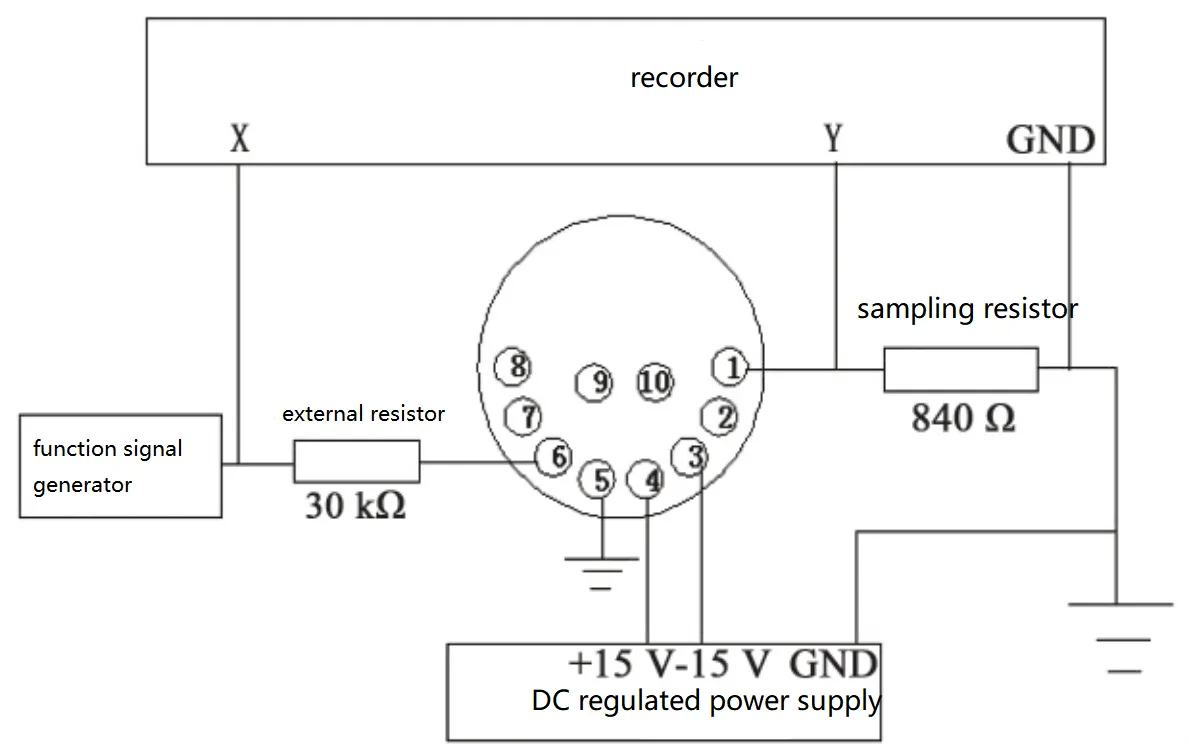
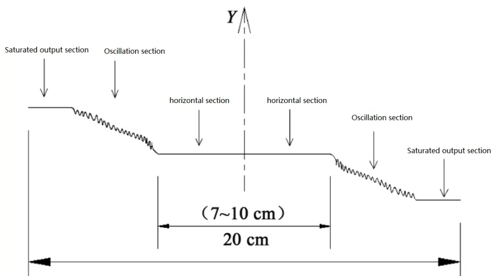
Typically, the excitation current is set as a triangular wave with a period of 60s and a peak of 20V, yielding recorder curves as depicted in Figure 4.
Through theoretical calculations, the maximum angle at which the pendulum can deflect in the absence of foreign objects can be determined, which corresponds to the maximum length of the horizontal segment of the curve above.
If, during actual testing, the length of the curve in the X direction does not reach the theoretical maximum value, it is reasonable to conclude that there are foreign objects inside the core of the instrument, affecting the deflection of the pendulum. In such cases, the accelerometer can be disassembled to investigate and remove the foreign objects before reassembly.
3.2 Wire Faults
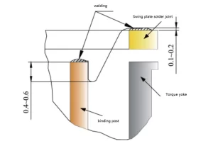
For wire welding in quartz flexure accelerometers, strict adherence to technical documents is essential. After wire welding, wire shaping (see Figure 5) should be conducted, which effectively prevents this fault.
4. Conclusion
Based on the analysis of the structure and working principle of the quartz flexure accelerometer, this article enumerates the causes and manifestations of faults, categorizes the manifestations and reasons of faults in detail, and proposes preventive measures for specific faults. Furthermore, the use of sensors with high stability also contributes to reducing the failure rate of accelerometers.
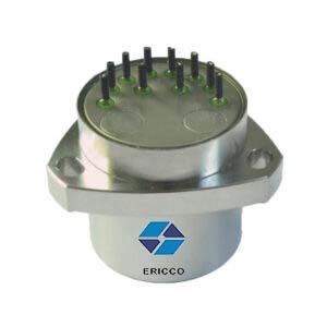
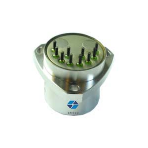
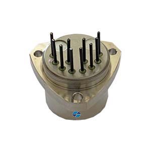
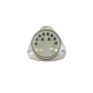
The high-performance quartz flexible accelerometer ER-QA-03A has an effective vibration acceleration of 6grms and adopts high-quality quartz crystal, which can adapt to high acceleration applications under various environmental conditions such as high temperature, high pressure, and high vibration environment, with extremely high reliability and stability.
In addition, the scale factor range of this accelerometer is 15-50ppm, and bias repeatability range is 10-50μg, which can achieve high-precision measurements. Apart from being widely used in aerospace and military fields, it is also extensively applied in automotive, medical, and research fields. In scientific research, it can also be used to study earthquakes, crustal movements, cosmology, and microgravity environments.
More Technical Questions
1. Improvement of Temperature Stability of Quartz Flexible Accelerometers
2. Quartz Accelerometers Advance Petroleum Logging Precision
3. Analysis of I/F Conversion Circuit of Quartz Accelerometer
4. MEMS Accelerometer Installation Error Correction Method
5. How to Improve the Impact Resistance of Quartz Accelerometer
6. Temperature Error Analysis of Quartz Accelerometer
Products in Article