Quartz accelerometer, which represents the acceleration of carrier by the output current, is the core component of high precision inertial navigation system, and has a series of advantages such as high precision and good anti-interference. The output current of the quartz acceleration sensor needs to be converted from analog to digital through the conversion circuit. There are two kinds of conversion circuits in common use: A/D conversion and I/F conversion, among which A/D conversion circuit has the advantages of low power consumption and simple circuit structure, but it has some problems such as quantization error and large output noise. The I/F conversion circuit has the advantages of high conversion accuracy, low temperature influence and no accumulation of errors, and is widely used in the analog-to-digital conversion of inertial navigation systems. However, in I/F circuit design, a larger threshold voltage has a larger range, but cannot obtain a higher resolution, and a smaller threshold voltage has a higher resolution, but cannot obtain a larger range, and the two indicators of range and resolution are contradictory. At present, I/F conversion +A/D conversion is mainly used. This method has been widely used in various I/F conversion circuits, improving the output equivalent of quartz accelerometer channel, but reducing the dynamic resolution of I/F conversion circuit.
1.I/F conversion circuit analysis
1.1 Basic principle of I/F conversion circuit
The I/F conversion circuit is composed of current integrator, positive channel hysteresis comparator, negative channel hysteresis comparator, logic processor, standard frequency circuit, positive channel analog switch, negative channel analog switch, positive channel feedback constant current source, positive channel feedback current and other modules, as shown in Figure 1.
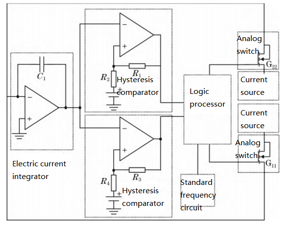
FIG.1 Quartz accelerometer IF conversion circuit structure block digram
In the I/F conversion circuit, the output current of the quartz accelerometer is integrated through the current integrator. When the output voltage of the current integrator reaches the threshold voltage of the hysteretic comparator, the output of the hysteretic comparator jumps from a low level to a high level, and the digital logic circuit opens the corresponding analog switch to discharge the current integrator. When the current integrator voltage is discharged to 0, the hysteresis comparator jumps from high level to low level, and the digital logic circuit receives the jump signal from high to low and controls the analog switch to disconnect. The I/F conversion circuit uses the output frequency of the hysteresis comparator as its output frequency.
1.2 Analysis of the main reasons for the contradiction between resolution and large range
In the traditional I/F conversion circuit, the level flip of the hysteretic comparator occurs only when the integrated voltage of the current integrator reaches the threshold voltage set by the hysteretic comparator. Figure 2 shows the conversion characteristics of the I/F conversion circuit at different threshold voltages.
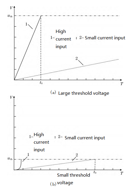
FIG. 2 Characteristics of quartz accelerometer IF conversion circuit under different threshold voltages
In FIG. 2(a), under a larger threshold voltage, the high-current input signal can be integrated to the threshold voltage in a short time, but if the input current signal is small, the current integrator cannot be integrated to the hysteresis comparison over a long period of time
The threshold voltage of the converter causes the conversion circuit to be unable to update the output for a long time, damages the real-time performance of the conversion circuit, and causes the circuit to be insensitive to small current signals, thus failing to obtain a higher resolution in a large range. As shown in FIG. 2(b), under a small threshold voltage, the input signal of a small current can be integrated to the threshold voltage in a short time. However, if the input current signal is large, the output of the integrator has reached the threshold voltage during the rise of the current because the current cannot be mutated, resulting in distortion of the circuit output during the measurement of a large current, so that a larger range cannot be obtained under high resolution.
The above analysis shows that the fixed hysteresis comparator threshold voltage is the main reason for the contradictory resolution and range of the I/F conversion circuit.
1.3 Improvement of I/F conversion circuit
According to the above analysis, if the influence of threshold voltage on the resolution and range of I/F conversion circuit can be eliminated, the problem of large range and high resolution of I/F conversion circuit can be solved. In this paper, a new I/F conversion circuit is proposed. Firstly, the threshold voltage of the I/F conversion circuit is set to be large enough to ensure the range of the conversion circuit. Secondly, the circuit structure and algorithm are improved to ensure that the output of the I/F conversion circuit can be updated in a short time under the condition of low current input. Ensure the I/F conversion circuit has a high resolution. In the circuit structure, two new comparators, one forward channel comparator, are added. One negative channel comparator; The positive input end of the forward channel comparator is grounded, the reverse input end is connected to the output end of the current integrator, and the output end is connected to the logic processor. The inverse-phase input end of the inverse-phase comparator is grounded, the positive input end is connected to the output end of the current integrator, and the output end is connected to the logic processor. After the output end of the logic processor, the analog switch corresponding to the positive channel comparator and the constant current feedback current source are added respectively.
2.Summary
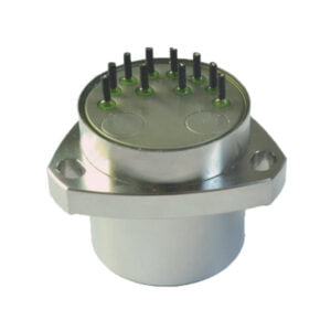
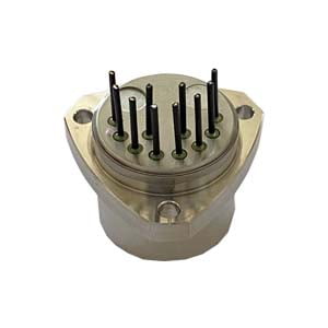
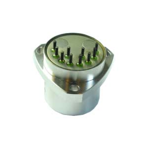
As a part of the acceleration channel, the precision of the I/F transform circuit has a direct impact on the accuracy of the inertial navigation system and the inertial measurement unit. The realization of the high-precision I/F transform circuit is important for the high-precision inertial navigation system. Matching with the high-precision quartz accelerometer ER-QA-01A can make it more outstanding in the application field.
More Technical Questions
1.Study on the Stability of Quartz Accelerometer Head
2.Temperature Error Analysis of Quartz Accelerometer
3.How to Improve the Impact Resistance of Quartz Accelerometer
4.MEMS Accelerometer Installation Error Correction Method
5.MEMS Accelerometer Packaging Technology
6.Calibration Method of Accelerometer
Products in Article