In order to further improve the accuracy of MEMS accelerometer, the measurement error of mems acceleration sensor must be reduced as much as possible. The measurement errors of it mainly include heating and noise errors, installation errors and non-orthogonal errors between axes. In order to such measurement errors, various errors must be compensated and corrected.
Methods for correction of heat and noise errors
When the MEMS accelerometer output is affected by heat and electronic noise, it can be said that the main influence of mems acceleration sensor output performance is heat and electronic noise. Electronic noise is usually a high frequency signal, so a low pass filter is added to the output of MEMS accelerometer to filter out the error caused by high frequency noise. After sampling and quantization, the filtered signal enters the DSP processor, and then performs digital filtering. The mean value of the quantization noise introduced is zero and has the characteristics of uniform probability density and white power spectral density. Therefore, it is assumed that the output of MEMS is affected by an additive white noise independent of the sampled signal and unbiased. So, by averaging multiple samples of MEMS output over a long enough period of time, the standard deviation of noise can be greatly reduced. After filtering and mathematical processing, the errors introduced by heat and electronic noise can be minimized.
Installation error model
As shown in the figure, x, y and z axes are the coordinate system of MEMS acceleration sensor, and X, Y and Z axes are the measurement coordinate system. Due to the installation error of MEMS acceleration sensor during installation, there is a certain deviation between x, y and z axes of sensor coordinate system and the axis of measurement coordinate system. In order to change the performance of MEMS accelerometer and obtain accurate results, Therefore, the installation error should be compensated. Its mathematical model is as follows:
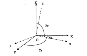
Taking the X-axis accelerometer as an example, when the sensor's sensitive axis coincides with the X-axis of the measuring coordinate system:
Ax1=Ox+Sxx·Gx
In the above formula:
Ax—X axis accelerometer’s output;
Ox—X axis accelerometer’s zero position error;
Sxx—X axis accelerometer’s scale factor ;
Gx—X axis gravitational acceleration component in the direction;
Taking the X-axis accelerometer as an example, when the sensor's sensitive axis does not completely coincide with the X-axis of the measuring coordinate system, the Y-axis and Z-axis components will be generated, then there are:
Ax2=Sxy·Gy+Sxz·Gz
In the above formula:
Gy—y axis component of gravitational acceleration along
Gz—z axis component of gravitational acceleration along
Sxy—y axis correction coefficient of the gravitational acceleration component along
Sxz—z axis correction coefficient of the gravitational acceleration component in the direction
When these two cases are taken into account, a mathematical model of the accelerometer's X-axis can be obtained:
Ax=Ax1+Ax2=Ox+Sxx·Gx+Sxy·Gy+Sxz·Gz
When extended to the case of three axes, the digital model of the three accelerometers on the probe is:
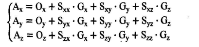
Among them:
Output of Ax,Ay,Az - x,y,z accelerometers;
Gx,Gy,Gz - the true gravitational acceleration component in the x,y,z direction;
Oi,Si - Each correction factor (12 in total)
The traditional 6-parameter correction method only considers the zero error and scale factor of each axis, and does not consider the error between each axis, that is, Syx=Sxy=Szx=Sxz=Szy=Syz=0. Since the installation of the acceleration sensor will inevitably generate installation errors, the non-orthogonal error between each axis is not considered. Therefore, the measurement error of the 6-parameter correction method without considering the non-orthogonal error between the axes is relatively large.
MEMS accelerometer installation error correction method
According to the established mathematical model of the installation error of MEMS acceleration sensor, there are two methods to calculate the 12 parameters in the formula. The first method is the special point method, which uses the special position of the measurement coordinate system to calculate and separate the coefficients O,S, and then the real acceleration component G of each axis can be obtained. This method has high accuracy requirements for the measurement equipment,so the correction costs are high; Another method is the automatic calibration method, which has the advantage of increasing the measurement accuracy without being affected by the environment and equipment accuracy. Its theoretical basis is: under static conditions, the output vector of the MEMS acceleration sensor is consistent with the acceleration of the earth's gravity. In a short time, the value of each parameter can be calculated by nonlinear optimization.
Principle of special point correction method
The method of special point correction is to put the MEMS acceleration sensor to be corrected in some special position by using the calibration table with high precision, so as to eliminate the coefficients in the model and calculate the parameters in the model.
Summary
The installation error analysis and correction of MEMS accelerometer is one of the important links, which can improve the accuracy and accuracy of the accelerometer. Of course, the choice of mems accelerometer is also a key link, ericco launched ER-MA-5 in zero bias stability can reach 5 μg, but also has the characteristics of small volume and light weight. It is believed that mems accelerometers with good cost performance and correct error correction methods will provide more stable and reliable data support for applications in related fields.
More Technical Questions
1.MEMS Accelerometer Packaging Technology
2.How to Improve the Impact Resistance of Quartz Accelerometer
3.Temperature Error Analysis of Quartz Accelerometer
4.Study on the Stability of Quartz Accelerometer Head
5.What is the Quartz Accelerometer Digital Closed Loop Servo Circuit?
6.Calibration Method of Accelerometer
Products in Article