1. Basic Introduction
Quartz accelerometers, as the core instruments of sensitive carrier line acceleration, are equipped in the inertial systems in various fields of land, sea, air and sky to ensure the basic needs of inertial navigation. However, since the parts in quartz flexible accelerometers use a variety of heterogeneous materials, the stress release, creep, aging, natural demagnetization of the material and other factors lead to the instrument output of the parameters with the change of time and temperature drift, and ultimately affect the navigation accuracy of the inertial system.
Especially with the development of temperature-control-free shortcut inertial navigation system, the output change caused by temperature change accounts for most of the proportion of the accelerometer parameter drift, therefore, the quartz flexible accelerometer temperature stability requirements are increasingly high. This paper focuses on the bias temperature stability, based on the quartz flexible accelerometer structure, discusses the program to improve the temperature stability of quartz flexible accelerometer parameters and improvement measures.
2. Analysis of bias temperature stability
The change of bias value with temperature is called bias temperature coefficient. The bias temperature coefficient of conventional accelerometers is about (30-100) μg/℃. With the miniaturization of the inertial system and low power consumption requirements, the accelerometer put forward the bias temperature coefficient <10 μg/℃ or even higher requirements.
The size of the bias value and its stability is an important guarantee for the high linearity of quartz flexible accelerometers, especially when measuring small accelerations. According to Eq. (1), the output bias of quartz flexible accelerometer is mainly due to the effect of disturbance moment Md, elastic recovery angle β, and servo amplifier input misalignment ΔU. Neglecting the circuit error, the bias error of the accelerometer in the thermal environment mainly comes from the change of the structural dimension of the pendulum part and the elastic recovery angle.

Among them, the changes in the structural dimensions of the pendulum parts mainly come from the mechanical mismatch caused by the assembly of dissimilar materials and the stress change of the membrane layer of the pendulum, while the changes in the elastic recovery angle mainly come from the mechanical mismatch caused by the assembly of dissimilar materials and the manufacturing error of the flexible beam.
3. Measures to improve the temperature stability of quartz flexible accelerometers
3.1 Improve the assembly process
The purpose of the measures on the assembly process is to reduce the asymmetric deformation caused by temperature change. It can be considered from two aspects of reducing deformation or reducing stress transfer.
(1) Improve bonding symmetry and reduce adhesive elastic modulus
The deformation of the capacitor pole plate surface is the coil skeleton through the adhesive transfer over, through the quantization of the amount of adhesive bonding glue of the pendulum parts, improve the symmetry of the bonding area and the bonding thickness, and at the same time, appropriately reduce the elastic modulus of the bonding agent, which can also reduce the deformation of the pendulum piece. Among them, the finite element simulation results of the relationship between the bias temperature coefficient of the accelerometer of the traditional structure and the thickness of the adhesive on both sides of the pendulum (thickness of the flexure beam 0.020 mm) are shown in Fig.1.
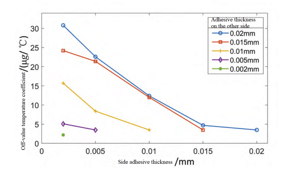
The more similar the thickness of adhesive on both sides of the skeleton, the smaller the bias temperature coefficient. Ideally, if the difference of adhesive thickness between the two sides of the pendulum is <0.005 mm, the bias temperature coefficient caused by <5 μg/℃. In reality, due to the fluidity of the adhesive, it is necessary to combine with the characteristics of the adhesive and the assembly process to study.
(2) Bonding by secondary transition
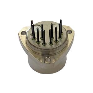
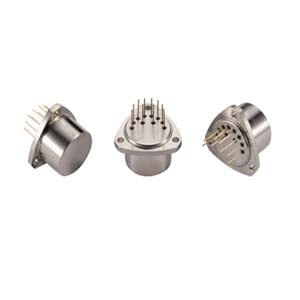
Add a glass piece between the pendulum and the skeleton, the glass piece is bonded axially to the pendulum and radially to the skeleton, the deformation of the skeleton will not directly cause the deformation of the pendulum, and the glass piece plays a role in isolating the transfer of stress, which can reduce the deformation of the pendulum and improve the temperature stability of the bias of the accelerometer, as shown in Fig. 2.
At 0.024 mm beam thickness, comparing the values before and after the structural improvement (32.7 μg/℃ before the improvement; 6.1 μg/℃ after the improvement), the optimized structure has obvious advantages in temperature stability.
3.2 Improved permanent magnet materials
Permanent magnet materials with high stability potential are mainly Alnico permanent magnet material and Samarium Cobalt permanent magnet material. Alnico permanent magnet material has high remanent magnetism, low temperature coefficient of remanent magnetism (-2×10⁻⁴/℃) and temperature coefficient of coercivity, but it is difficult to meet the high stability requirements of quartz accelerometer because of low coercivity and poor resistance to external interference. Samarium cobalt permanent magnetic material has high coercivity (Hcj>25kOe), strong resistance to environmental interference, and at the same time, it can reduce the remanent temperature coefficient of remanence by using the principle of compensation of heavy rare earth elements, which significantly improves the temperature stability of the accelerometer's scaling factor, and therefore it becomes the preferred permanent magnetic material for high-precision accelerometers.
3.3 Improvement of magnetic circuit design
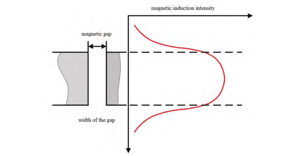
The working air gap magnetic field (B1+B2) is not only related to the permanent magnet material, but also related to the working air gap magnetic field uniformity and magnetoresistance. In the most ideal magnetic circuit, it should be the same B value at any position, but due to volume and spacing limitations, the uniform distribution of magnetic field is difficult to realize. As a second best, the magnetic circuit design should make the magnetic field distribution as symmetrical as possible, so that the B1+B2 is as constant as possible, as shown in Fig.3.
The connection of the accelerometer magnetic circuit structure includes the connection between the magnet and the magnetic guide plate, and the connection between the magnet and the magnetic guide ring, etc. At present, the traditional connection method is adhesive bonding. The creep of the adhesive with temperature will affect the magnetic circuit permeability, electromagnetic force center position, etc., and reduce the temperature stability of the scale factor. As shown in Fig. 4, under the Maxwell magnetic field finite element simulation software environment, the changes in the output electromagnetic moment are calculated as 160 ppm/1 μm and 242 ppm/1 μm for the connection of the magnet steel and the permeability ring, and the connection gap between the magnet steel and the pole piece is displaced due to creep.
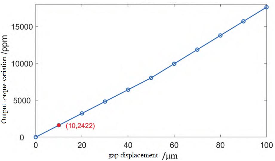
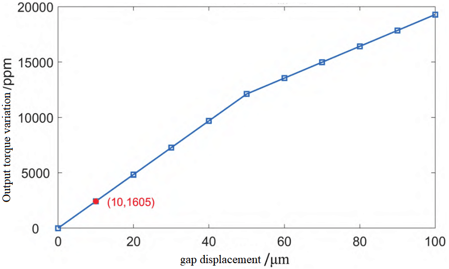
From the creep analysis of the adhesive, it can be seen that during the application of temperature change, deformation of about 0.2 μm will be generated, and the accelerometer scale factor will change (32-48) ppm, and the scale factor change will be even larger if an adhesive with a smaller modulus of elasticity is used.
With the development of laser technology, adhesive-free joining of different materials is possible. A perforation is designed in the middle of the magnetic pole piece and the magnetic guide ring respectively, which can increase the axial magnetoresistance, reduce the axial magnetic line of force dispersion, improve the utilization of the radial magnetic circuit, and at the same time, it can be used as a channel for laser welding. The use of laser welding technology instead of adhesive bonding avoids adhesive creep and allows for a more stable magnetic circuit connection design.
4.Conclusion
This paper has provided some insights into improving the temperature stability of quartz flexible accelerometers and offered practical solutions to mitigate these challenges. Various measures to improve temperature stability have been explored in this paper, with a particular focus on assembly improvements. Improvements in magnetic materials and magnetic circuit design are also discussed to further increase temperature stability. Through advances in design and assembly techniques, these measures can significantly improve the temperature stability of quartz flexible accelerometers, thereby ensuring more reliable and accurate performance in critical applications.
Notably, ER-QA-03A1 developed by Ericco, the high performance quartz flexible accelerometer uses high-quality quartz crystals to achieve high precision acceleration measurement with extremely high reliability and temperature stability. After long-term use, its accuracy can also be improved by temperature compensating. With Scale factor repeatability ≤15 ppm and bias repeatability ≤10μg, its special flexible construction enables it to adapt to high acceleration applications under various environmental conditions, such as high temperature, high pressure and high vibration environments.
I will appreciate it if you find this article helps you a lot. Read the following articles to get more information bout flexible quartz accelerometers.
Add Your Heading Text Here
1. Quartz Accelerometers Advance Petroleum Logging Precision
2. Analysis of I/F Conversion Circuit of Quartz Accelerometer
3. How to Improve the Impact Resistance of Quartz Accelerometer
4. Temperature Error Analysis of Quartz Accelerometer
5. Study on the Stability of Quartz Accelerometer Head
6. What is the Quartz Accelerometer Digital Closed Loop Servo Circuit?
Add Your Heading Text Here