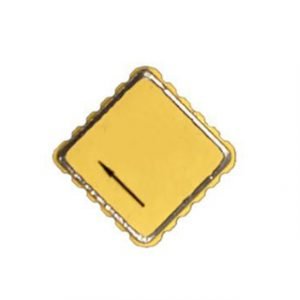
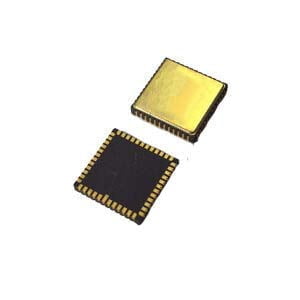
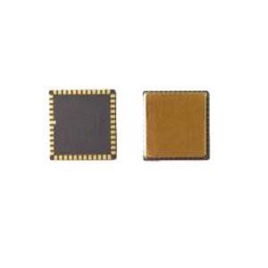
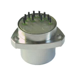
1.MEMS accelerometer
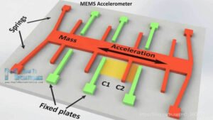
The schematic diagram of the MEMS accelerometer is shown in the figure below, in which the mass is supported by springs, so that it can only be displaced in a predetermined direction to detect acceleration in a specific direction; the green part is the fixed electrode plate Fixed plates. The detection principle is that when the mass block feels the acceleration, it will be displaced in the corresponding direction, so that the capacitance of the two parallel plate capacitors C1 and C2 formed by the fixed electrode plates will change, and the capacitance value can be converted into the corresponding acceleration.
2.MEMS gyroscope
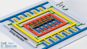
The detection principle of MEMS gyroscopes is similar to that of MEMS accelerometers but requires the use of a Coriolis force corresponding to the Coriolis effect.
The Coriolis force comes from the inertia of the motion of the object. The particle moving in a straight line in a rotating system has a tendency to continue to move along the original direction of motion due to the effect of inertia. However, since the system itself is rotating, in after a period of motion, the position of the particle in the system will change, and the direction of its original motion trend will deviate to a certain extent if observed from the perspective of the rotating system.
As shown in the figure above, when a particle moves in a straight line relative to the inertial system, its trajectory is a curve relative to the rotating system. Based on the rotating system, we believe that there is a force that drives the trajectory of the particle to form a curve, and this force is the Coriolis force.
According to the theory of Newtonian mechanics, taking the rotating system as the frame of reference, the tendency of the linear motion of the particle to deviate from the original direction is attributed to the action of an external force, which is the Coriolis force. From the point of view of physics, Coriolis force, like centrifugal force, is not a real force, but the embodiment of inertial action in a non-inertial frame.
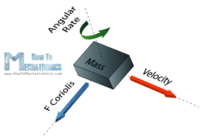
With the above introduction to the Coriolis force, it is easy to look at the principle of the gyroscope. As shown in the figure below, the green arrow represents the input angular velocity, and the right-hand screw can be grasped to know that the dotted line in the green arrow is the direction of the angular velocity; the red arrow represents the driving speed of the mass block, and the resulting Coriolis force is blue Arrow, the right hand is held from the direction of angular velocity (dotted line up) to the opposite (blue arrow) of velocity (red arrow).
The following describes the schematic diagram of the internal principle of the gyroscope. As shown in the figure below, carefully look at the three places with words, the left is the driving direction of the motion of the driving mass, the right is the input angular velocity direction, and the middle is the sensitive direction of the mass and the sensor.
Due to the introduction of the Coriolis force (Coriolis force), it is easy to explain that the mass block will be displaced in the sensing direction, which will cause the capacitance value of the parallel plate capacitor to change. The detected capacitance value can be converted to the input angular velocity.
3.MEMS magnetometer
It uses the Hall effect or the magnetoresistance effect to measure the Earth's magnetic field. In fact, almost 90% of sensors on the market use the Hall effect, and here's how it works.
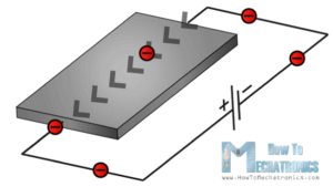
If we had a conductive plate like the one shown in the image below, and we set the current to flow through it, electrons would flow directly from one side of the plate to the other.
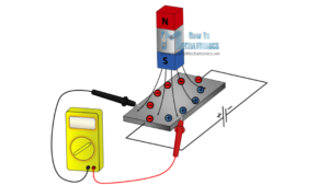
Now, if we put some magnetic field near the plate, we disturb the straight flow of electrons, the electrons will be deflected to one side of the plate, and the positive charges (holes) will be deflected to the other side plate. That is, if we now put the meter between the two sides, we will get some voltage, which depends on the strength and direction of the magnetic field and detecting this voltage can be converted into the strength and direction of the magnetic field.
The other 10% of sensors on the market use the magnetoresistive effect. These sensors use materials that are sensitive to magnetic fields, usually composed of iron (Fe) and nickel (Ne). Therefore, when these materials are exposed to a magnetic field, their resistance changes.
More Technical Questions
1.How do MEMS gyroscopes work?
2.Why do we Need Accelerometer?
3.MEMS gyroscope VS FOG: What’s the difference between them?
4.What is the Purpose of the Accelerometer Senor?
5.Where are MEMS Gyroscopes Used?
6.How accurate is MEMS gyroscope?
Products in Article
