Many people are not aware of the north seeking schemes commonly used in gyroscopes. Today after understanding the common north seeking schemes below, you can choose different gyroscope north seeking solutions according to different applications.
The north seeking principle of the gyroscope is to measure the component of the earth's rotation velocity in the horizontal plane through its sensitive axis, and then get the Included Angle with true north.
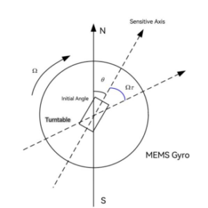
In an ideal situation, the gyroscope's sensitive axis is parallel to the horizontal plane, pointing in the direction of true north. In this case, its static output can be expressed as:
Ωo=Ωa cosφcosθ
φ represents the local latitude, Ωa represents the horizontal component of the Earth's rotation angular velocity, and θ represents the initial north. As shown in the picture:
Based on MEMS gyroscope, the collection position and algorithm of north seeking are different, which can be divided into static two-position, four-position, multi-position north seeking, and continuous rotation dynamic north seeking.
The static two-position, four-position and multi-position north seeking schemes all place the gyroscope on the turntable and rotate at a fixed Angle to collect the output of the gyroscope at a specific position. After calculation, the Angle between the sensitive axis and the true north direction is obtained. These schemes are completed based on the turntable plane of the rotation control system. The difference is the rotation Angle, the number of collection position, the required time and the calculation method.
Two-position north seeking
It means that the attitude instrument is placed on a mechanical turntable ,which controls the attitude instrument at two positions 180° apart to collect the gyroscope-sensitive earth angular rate component value Ωa. The output of gyroscope separated by 180° can offset the constant drift by the solution method, and the time interval between the two positions should be controlled within a short time.
First, place the sensitive axis of the gyro parallel on the turntable; second, select the initial position and collect the output of the gyroscope; third, immediately rotate the turntable to a position 180° apart from the initial position and collect the output of the gyroscope in this position. The output of the gyroscope in the two positions is ω0,ω180 as shown below:
ω0=Ωa cosφcosθ+τ+δg
ω180=Ωa cosφcos(θ+180°)+τ+δh
τ represents constant drift of gyro angular rate, and δg and δh represent gyro noise. The time interval from the initial position to the 180°position is so short that they can be considered equal. It can be obtained from the above two formulas:
Ωa cosφcosθ=(ω0-ω180)/2
The final value of the Included Angle in the true north direction is as follows:
θ=arccos[(ω0-ω180)/2Ωa cosφ]
Four-position north seeking
Four-position north seeking is based on two-position north seeking. By rotating the turntable, the attitude instrument is controlled at four positions 90° apart to collect the values of the gyro-sensitive Earth angular velocity components respectively. The time to move to the next position after collecting one position should be as short as possible.
The results of the four-position north seeking scheme are not affected by the local latitude, gyro scale factor and bias, and the trend item error can be reduced by following the sequence of 0°, 180°, 90° and 270°. For situations where the requirement of the north seeking time is not too strict, the improved four-position north seeking scheme can be adopted.
Multi-position north seeking
Based on two-position north seeking and four-position north seeking, multi-position north seeking is a north seeking scheme in which the output of gyroscope is collected from n positions separated by Angle Δθ during 360° rotation. For example, the output of 18 groups of gyroscopes in 36 positions is collected 10° apart. As more locations are collected, the precision of the gyroscope sensitive to the earth rotation rate becomes higher, and the precision of north seeking becomes higher.
Continuous rotation dynamic north seeking
It means that the gyroscope is placed on a precision turntable, which drives the sensitive axis of the gyroscope to rotate at a constant speed, and the rotational rate is artificially controlled. At the same time, the output of MEMS gyroscope under rotation was collected, and then the north Angle was calculated.
Compared with static north seeking, continuous rotation north seeking is less affected by noise and constant drift, and can achieve higher precision north seeking in a shorter time. At present, the most used method is the least square fitting method to calculate the north seeking Angle.
Although the continuous rotation dynamic north seeking scheme can suppress the constant drift and random error of the gyro by controlling the rotation of the turntable, it needs a more complex algorithm and the accuracy of the turntable needs to be high enough to maintain a stable and constant rotation speed.
More Technical Questions
1.The Principle and Application of North Finder
2.Do You Know the FOG North Finder?
3.Application of MEMS Accelerometer in North Finder
4.How MEMS ‘accelerate’ North Finder
5.Application of North Finder in Mining Industry
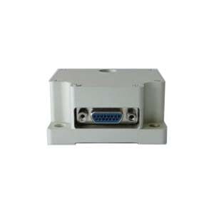
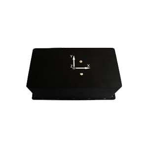
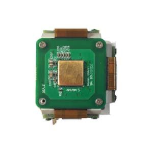
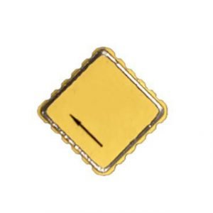
Products in Article