The borehole north finding system based on MEMS north finder needs to overcome the complex environment in borehole north finding. Shock vibration is one of the main factors affecting the accuracy of borehole north finding by MEMS north finder. When shock vibration occurs, the core component of MEMS gyro is sensitive not only to the horizontal component of earth rotation, but also to the angular velocity component generated by shock vibration interference. Therefore, in order to improve the precision of borehole north finding while drilling, it is necessary to compensate the error of MEMS north finder under shock vibration.
1.The influence of vibration on borehole north finding
When the drill bit is drilling, it will not only cause the tilting of the base of north seeker, but also cause high frequency interference due to shock vibration. In practice, the situation is very complicated, MEMS gyroscope will be sensitive to other signals in addition to the Earth's angular rate component, such as drilling the base Angle to produce additional angular speed. The final output of a MEMS north seeker consists of a superposition of many signals. In this section, the Angle vibration of drilling bit is taken as the main research object, and the error caused by it is analyzed. Bit drilling will make the transverse roller and pitch axis of MEMS north finder do different angular vibration, the specific characteristics are as follows:

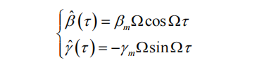
In Formula 1, Bm and rm represent the vibration amplitude of the MEMS north seeker around the pitch axis and transverse roller axis, where is the vibration frequency, then the influenced angular velocity brought about by the drilling bit is:
On the basis of two-position north finding, the output after adding only vibration error is:

The north finding Angle obtained by the above formula 3 is:
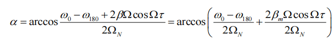
The above equation 4 is approximated by the first expansion of Taylor's formula

Among them, it belongs to the north-seeking error introduced by drill bit drilling. As can be seen from formula 4, when the sensitive axis of the gyroscope approaches north or south, it approaches 1 and has the smallest impact on error; when it approaches east-west, it approaches 0 and has the greatest impact on error. At present, there are two main ways to reduce downhole vibration errors while drilling: The first is to install shock insulation material at the bit to physically buffer and reduce the impact of shock and vibration on the north finding accuracy of MEMS gyroscope. This method will cause the volume of the whole north finding system to increase and affect the drilling of the bit; The second method is to reduce the impact of shock vibration by means of algorithm compensation, such as using an accelerometer that can sense angular velocity and disturbance angular velocity at the same time to compensate the gyroscope output signal, but the accuracy of this method is affected by the accuracy of the accelerometer. This paper presents a method based on multi-resolution analysis to solve the effect of bit vibration on the accuracy of the north seeker.
2.Multi-resolution analysis of borehole north finding system
During drilling, the accuracy of north seeker is affected by various and complex factors. The compensation effect of installing physical anti-vibration materials and using continuous rotation north finding scheme is not very ideal. The effect of north finding while drilling is the error of multiple interference superposition, which makes it difficult for MEMS north seeker to achieve the ideal precision based on the above method. It is very practical and significant to use the filtering method to compensate the complex effects while drilling.
Multi-resolution analysis method is a fast transform algorithm using orthogonal wavelet basis, which is widely used in practical engineering applications and more convenient to solve problems, also known as Mallat algorithm. The signal is decomposed as follows
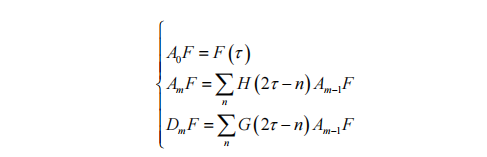
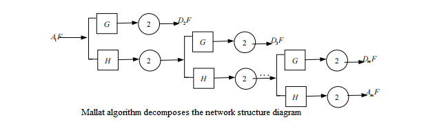
Mallat algorithm is a progressive algorithm, that is, the initial signal frequency band is divided into high frequency and low frequency parts, and then the low frequency part is used as the high frequency part of each layer below, which is divided by half band. The signal decomposition network structure of Mallat algorithm is shown in Figure 7 below.
Mallat is designed to wavelet transform the filtered signal, remove the noise coefficient, and retain the signal wavelet coefficient, that is, to achieve wavelet filtering. Wavelet threshold method is the easiest method to achieve this purpose, and it is also the most commonly used in practice.
The collected gyroscope output is the fusion data of signal and noise. The noise is dispersed relative to the useful signal in the wavelet domain, and the wavelet coefficient of the signal is greater than that of the noise. By setting a threshold, the wavelet coefficient below the threshold is set to 0, the wavelet coefficient at and above the threshold is retained, and then the signal reconstruction of the processed wavelet coefficient is carried out to recover useful signals, and the filtering of Mallat algorithm can be realized. The signal reconstruction algorithm is as follows:

3.Error compensation experiment and results
In order to verify the effectiveness of Mallat algorithm in compensating the shock vibration error of MEMS north finder, a shock vibration experiment was set up. Firstly, the wavelet base suitable for Mallat algorithm is selected. In the borehole north finding while drilling system, the useful signal output of MEMS gyro is the low-frequency part, and borehole north finding should be completed in a short time, resulting in limited data points collected. Therefore, the wavelet base with higher vanishing moment and better linear phase should be selected. To ensure that the energy after wavelet transformation is concentrated in the low frequency part and reduce the edge distortion after signal reconstruction.
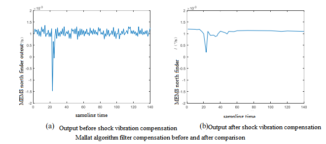
At the beginning of the experiment, the attitude instrument based on MEMS north seeker was fixed on the turntable and powered up to preheat to ensure the normal data. The sampling frequency was set to 100 Hz. To simulate the downhole scene, the impact shaker sets 1000g impact and 20Hz vibration frequency. First, the data output is collected in the static state, and the impact and vibration interference of MEMS attitude instrument is simulated by the console during drilling while drilling. The Mallat algorithm is used to decompose and then reconstruct.
It can be seen from the comparison of Mallat algorithm's decomposed and reconstructed filtering results that this algorithm has a good filtering effect on the vibration and noise influence of MEMS north seeking system while drilling.
Summary
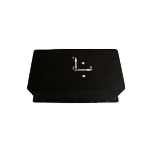
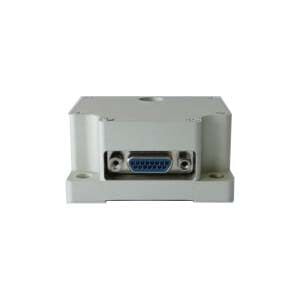
At present, MEMS north finder has had a more mature development, Ericco's cost-effective three-axis MEMS north finder ER-MNS-05 and smallest size MEMS three-axis north finder ER-MNS-06 are fully equipped with the function of fighting against harsh monitoring environment, welcome to understand.
More Technical Questions
1.Technical analysis of MEMS direction alignment instrument for mining
2.Research on downhole north seeker
3.Research on orthogonal monitoring technology of north finder
4.Modeling and filtering in signals collected by FOG north seekers
5.Error Modeling and Compensation Analysis of North Finder Based on FFT
6.Research and use of north finder for mining drilling rigs
Products in Article