The concept of IMU
The inertial measurement unit, referred to as IMU, is a device that measures the three-axis attitude angle (or angular velocity core) and acceleration of an object. Gyroscopes and speedometers are devices of an inertial navigation system.
The IMU has a built-in speed sensor and gyroscope, which can measure linear acceleration and rotational angular velocity in three directions.
Working principles for IMU
IMU is based on Newton's laws of mechanics. By measuring the acceleration of the carrier in the inertial reference system, integrating it over time, and transforming it into the navigation coordinate system, the speed and yaw angle in the navigation coordinate system can be obtained. and location information.
The inertial measurement unit is a device that measures the three-axis attitude angle (or angular rate) and acceleration of an object. Generally, an IMU contains three single-axis accelerometers and three single-axis gyroscopes. The accelerometer detects the acceleration signals of the object in three independent axes of the carrier coordinate system, while the gyroscope detects the angular velocity signal of the carrier relative to the navigation coordinate system, and measures the object's position in the carrier coordinate system. The angular velocity and acceleration in three-dimensional space are used to calculate the attitude of the object. It has very important application value in navigation.
The principle of an inertial measurement unit is very similar to taking small steps in the dark. In the dark, due to the error between your estimate of the step length and the actual distance walked, as you take more and more steps, the difference between your estimated position and the actual position will become farther and farther. When taking the first step, the estimated position is relatively close to the actual position; but as the number of steps increases, the difference between the estimated position and the actual position becomes larger and larger. This method is extended to three dimensions, which is the principle of the inertial measurement unit.
Therefore, in layman's terms, the inertial measurement unit IMU is a strapdown inertial navigation system. The system consists of three acceleration sensors and three angular velocity sensors (gyros). The accelerometer is used to feel the acceleration component relative to the vertical line of the ground. The speed sensor is used to get a feel for the angle information.
It is worth noting that the inertial measurement unit provides relative positioning information. Its function is to measure the movement route of the object relative to the starting point, so it cannot provide information about your specific location. Therefore, it is often combined with GPS. Used together, when the GPS signal is weak in some places, the IMU can play its role, allowing the car to continue to obtain absolute position information and not get "lost."
How three-axis accelerometer works
Most three-axis acceleration sensors use piezoresistive, piezoelectric and capacitive operating principles. The resulting acceleration is proportional to changes in resistance, voltage and capacitance and is collected by corresponding amplification and filtering circuits. This is the same principle as an ordinary acceleration sensor, so through certain technology, three single axes can be turned into a three-axis. For most sensor applications, a two-axis acceleration sensor is sufficient.
Working principle of three-axis gyroscope
The working principle of the three-axis gyroscope is based on the gyro effect. When the gyroscope's axis of rotation is perpendicular to the direction of the force, it feels the force, which creates a torque that causes it to rotate in the coordinate system. The three gyroscopes in a three-axis gyroscope are mounted on three mutually perpendicular axes. They sense the angular velocity on the x, y, and z axes respectively, and output the signals to relevant circuits for processing.
Application areas and uses of IMU
Inertial navigation IMU has a wide range of application scenarios and is often used for pointing, steering and guidance monitoring, rock soil monitoring, etc. in advanced mining/drilling equipment, ships, automobiles, drones, robots, oil exploration, bridge exploration, high-rise buildings, iron towers, dams, etc. , navigation and positioning of transportation vehicles such as mining and missiles, and north-finding positioning in geodetic/land mobile mapping systems.
In the automotive field, inertial navigation IMU can help vehicles achieve autonomous driving and traffic jam identification, improving driving performance and safety. In land vehicles, IMUs can be integrated into GPS-based car navigation systems or vehicle tracking systems to provide dead reckoning capabilities to the system and the ability to collect as much accurate data as possible about the vehicle's current speed, turn rate, heading and inclination and acceleration, combined with the vehicle’s wheel speed sensor output and reverse gear signal for purposes such as better traffic collision analysis. The ER-MG2-300/400 developed by ERICCO is a navigation-grade MEMS gyro sensor with a measurement range of up to 400 degrees/second and a bias instability of 0.05°/hour. It is designed for precision attitude in high-performance IMU/AHRS. Designed for azimuth measurement, positioning, navigation, guidance/GNSS-assisted INS, aviation/marine/land mapping/measurement systems/unmanned aerial vehicle/AUV and navigation-level MEMS weapon systems.
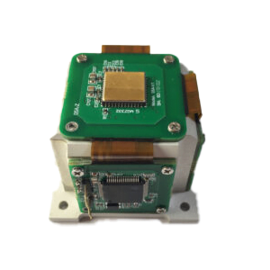
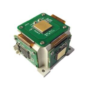
In the aviation field, inertial navigation IMU can realize motion control such as aircraft climbing, descending, turning, taxiing, etc., improving flight safety and accuracy. In a navigation system, data reported by the IMU is fed into a processor to calculate altitude, speed, and position. ER-MIMU-01 developed by ERICCO uses high-quality and reliable MEMS accelerometer and gyroscope. It communicates with the outside through RS422. The baud rate can be flexibly set between 9600~921600. The communication baud rate required by the user can be set through the communication protocol. Equipped with X, Y, Z three-axis precision gyroscope, X, Y, Z three-axis accelerometer, with high resolution, it can output the original hexadecimal complement of X, Y, Z three-axis gyroscope and accelerometer through RS422 code data (including gyroscope hexadecimal complement) numerical temperature, angle, accelerometer hexadecimal temperature, acceleration hexadecimal complement); it can also output gyroscope and accelerometer data that have been processed by underlying calculations Floating point dimensionless value.
One of the earliest devices was designed and built by the Ford Instrument Company for the U.S. Air Force and was intended to help aircraft navigate in flight without requiring any input from outside the aircraft. The device, known as a ground position indicator, shows the pilot the aircraft's longitude and latitude relative to the ground once the pilot inputs the aircraft's longitude and latitude during takeoff.
A major disadvantage of using IMUs for navigation, then, is that they are often subject to cumulative errors. Because the guidance system continuously integrates acceleration versus time to calculate velocity and position (see dead reckoning), any measurement error, no matter how small, accumulates over time. This results in "drift": an increasing discrepancy between where the system thinks it is and where it actually is. The ER-MG-067 developed by ERICCO is a high-precision tactical-grade MEMS gyroscope with an instability deviation of 0.3 degrees/hour and an angular random walk of 0.125°/√h. It is a single-axis MEMS angular rate sensor. (gyroscope), capable of measuring angular velocity up to ±400°/s, and the digital output complies with the SPI slave mode 3 protocol. Angular rate data is represented as 24-bit words.
So if you want to know more about how to correct errors in the IMU and learn more about the imu, you can find useful content in "More Technical Issues". If you are interested in the product, you can click "Products in Articles". If you have any questions, please leave your comments in "Ask a Question" below.
More Technical Questions
1.What are the advantages of MEMS IMU?
2.What are the Application Scenarios of the IMU?
3.The Difference Between Gyroscope, Compass, IMU, MEMS
4.Calibrating Processing of MEMS IMU ER-MIMU-02
5.Software Debugging of MEMS IMU ER-MIMU-01!
6.What are the Components in IMU?
Products in Article