Zero drift refers to errors in the heading and position measured by the Inertial Navigation System (INS) when it does not receive any external measurement signals. This error is caused by the drift and noise caused by the inertial device itself. Zero drift is a major problem for INS because it can cause the accuracy of INS to decrease, which in turn affects the accuracy and reliability of navigation.
In INS, zero drift refers to the phenomenon that when the inertial device rotates or vibrates in space, the output signal of the inertial device is offset due to the mechanical structure or circuit noise inside the device. This offset signal can be mistaken for a true motion signal, resulting in a deviation of INS heading and position information.
The occurrence of zero drift is determined by the physical characteristics of inertial devices. Inertial devices usually use sensors such as gyroscopes and accelerometers to detect motion states. In the state of motion, these sensors are subject to external interference and noise, causing the output signal to shift. In addition, the operating temperature of the inertial device, mechanical vibration and other factors will also affect the generation of zero drift.
In order to solve the zero drift problem, INS usually uses calibration techniques. The calibration technique is to process and adjust the inertial device to make its output signal more accurate and stable. Common calibration techniques include zero bias calibration, scale factor calibration, axial calibration and so on. In addition, methods such as composite navigation system can be used to combine different types of navigation systems to improve the accuracy and reliability of navigation.
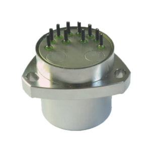
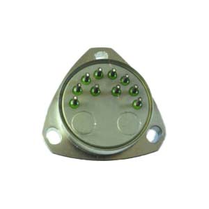
It is one of the important indexes to measure the precision of gyroscope.Denotes that when the input angular rate is zero, it measures the dispersion degree of the output of the gyroscope around its mean value (zero deviation).The equivalent angular rate of the corresponding standard deviation of the output within a specified period of time, also known as zero drift.The units are degrees per hour, degrees per second.The ER-MG2-50/100 has a bias instability of 0.01 to 0.02°/hr and an angular random walk of 0.0025 to 0.005°/√hr, is capable of measuring angular velocities up to ±100°/s, and has a digital output compliant with the SPI slave Mode 3 protocol. Angular rate data is expressed as 24-bit words. It is designed for north finding, pointing, initial alignment/gyroscope tools, mining/drilling equipment, weapons/drone launch systems, satellite antennas, target tracking systems, etc. Due to its high performance, it can also be used for high-precision attitude measurement, stability control, positioning, navigation-grade MEMS IMU/ INS, land surveying/land mobile mapping systems, railway train systems, etc. As a result, it is the best, cost-effective, robust, reliable, small, lightweight, and low-power alternative to low and medium navigation grade fiber optic gyroscopes with north finding, precision attitude measurement, inertial positioning, and navigation.
The occurrence of zero drift is determined by the physical characteristics of the inertial device. Inertial devices usually use sensors such as gyroscopes and accelerometers to detect the state of motion. In the state of motion, these sensors will be subjected to external interference and noise, resulting in the output signal offset. In addition, the operating temperature of the inertial device, mechanical vibration and other factors will also affect the generation of zero drift. In order to solve the zero drift problem, the inertial navigation system usually adopts calibration technology. Calibration technology is to process and adjust the inertial device to make its output signal more accurate and stable. Common calibration techniques include zero bias calibration, scale factor calibration, axial calibration and so on. In addition, methods such as integrated navigation system can be used to combine different types of navigation systems together to improve the accuracy and reliability of navigation.
The method to calculate the gyro zero-bias stability is to collect a section of data, remove the trend term, and then calculate the mean square error.So obviously, the longer the sampling time, the longer the smooth data length, the better the zero-biased stability value.Therefore, sampling time is also one of the parameters to be considered when evaluating accuracy.
More Technical Questions
3.What are the advantages of MEMS IMU?
4.How accurate is MEMS gyroscope?
6.What Data Format is High Performance MEMS Gyro
Products in Article