MEMS gyroscope is a device based on MEMS technology. As an emerging technology in the 21st century, MEMS gyroscope is constantly being improved. However, as a technology, there will always be errors, so corresponding measures need to be taken to make up for these errors.
In the last article, we introduced the basic information of MEMS errors and calibration. In this article, we will introduce the specific calibration method in detail. The calibration of MEMS gyroscope is mainly divided into non-autonomous calibration and autonomous calibration.
Non-autonomous calibration: This kind of calibration requires the assistance of well-structured precision instruments, such as high-precision turntables, centrifuges, shakers, etc.
Autonomous calibration: Without the assistance of high-precision instruments, this calibration is completed using external reference excitations provided by the local gravity field, earth rotation angular velocity, uniform magnetic field, etc.
Below we will introduce the calibration method of MEMS gyroscope.
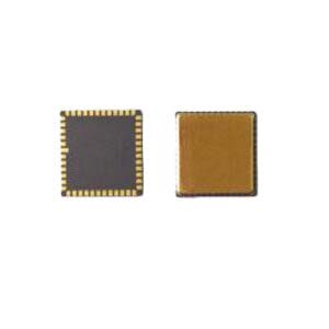
Since the Earth's rotation angular velocity is a weak signal, that is, the Earth's rotation velocity is hidden in larger noise, and only a gyroscope with medium or higher precision can sense it keenly. Therefore, the calibration of a gyroscope requires more external excitation than an accelerometer. Such as large instrument centrifuges, motion rate meters, etc., as well as other external stimuli, such as electrostatic force, gravitational acceleration, etc. MEMS gyroscope developed by Ericco are calibrated to achieve high performance when leaving the factory. For example, ER-MG2-50/100, its parameters can reach 0.01-0.02°/hr bias instability and 0.0025-0.005°/√ hr angle random walk.
1. Non-autonomous calibration
Non-autonomous calibration relies on a mechanical platform to rotate the IMU (Inertial Measurement Unit) to different, predefined, precisely controlled orientations and angular rates. Experiments show that due to the small amplitude of the earth's rotation rate, the accuracy of calibrating gyroscopes using the static six-digit method is unacceptable, and calibrating gyroscopes requires greater rotational excitation. Greater rotational excitation is provided through a turntable with an accuracy of 0.1°/s, and the accelerometer and gyroscope are calibrated separately. Therefore, it is not possible to estimate the trinity misalignment between gyroscope and accelerometer.
This solution is optimized for the two shortcomings of multi-position calibration of gyroscopes:
The weak signal of the Earth's rotation cannot be sensed.
Strict requirements on initial values.
This solution does not require leveling, but ignores the difference in angular velocity between the main axis and the counter-rotating platform. The accelerometer and gyroscope are calibrated independently, so calibration accuracy depends on alignment.
In order to solve the problem that gyroscope calibration is sensitive to the input angular rate and the angular rate is affected by the difference between the spindle speed and the counter-rotating platform speed, the study further analyzed the possible error sources on the turntable or centrifuge, and established the corresponding coordinate system. Combining the output of 16 specific positions, the angular velocity derived from the centrifuge, the input specific force, and the static error model of the gyroscope, the expression of the bias coefficient is obtained to improve the error compensation accuracy.
In order to respond to acceleration and independent calibration of the gyroscope, misalignment between the three axes is ignored. A 2008 study used the fact that the dot product of accelerometer and gyroscope outputs is directly related to the dot product of the Earth's rotation rate and gravitational acceleration to increase the constraints between accelerometers and gyroscopes. However, the accuracy of the gyroscope error parameters obtained by this method needs to be improved.
Although non-autonomous calibration can achieve higher accuracy through the introduction of turntables, centrifuges, etc., many scholars have also noticed that the introduction of large equipment will also bring new errors. And when sensors are integrated in a frame, the crosstalk between the two also needs to be considered. Therefore, it needs to be further improved through fine division of error sources and optimization of the model.
2.Autonomous calibration
For the autonomous calibration of gyroscopes, in addition to the earth's rotation angular velocity, some other auxiliary excitations are also used, such as accelerometers, magnetometers, etc. The following mainly explains the autonomous calibration of gyroscopes under different auxiliary excitations:
2.1 Multiple locations
Figure 1 shows that the experiment achieved the estimation of 12 position parameters through four measurements, and the gyroscope calibration can be completed with only manual rotation. However, there are many assumptions set, and the robustness and versatility of its algorithm cannot be guaranteed.
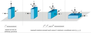
Figure 1 Orientation of 3D gyroscope during four calibration measurements
2.2 Accelerometer
First, the accelerometer is calibrated through the six-digit method, and then the wheel speed is determined with the help of the accelerometer. A solution is proposed to calibrate the gyroscope by combining the accelerometer with the bicycle wheel, thereby eliminating the error caused by the accelerometer that will be superimposed on the gyroscope. In addition, theoretically, the gravity vector of the accelerometer should be equal to the gravity vector calculated through the gyroscope output. Therefore, some scholars use a combination of motion and static, using the static error parameter as the initial value, and eliminate it by introducing the earth's gravitational field. It eliminates the limitation of sensor orientation, allowing the gyroscope to be calibrated by simply rotating it. However, the gyroscope must rotate in a fixed structure, so the experiment utilizes the known rotations between positions in a multi-position calibration, relating the first and last quaternions of each rotation to the corresponding 24 reference positions, This eliminates the need for precise alignment during the calibration process, thereby achieving freedom of rotation plane.
2.3 Magnetometer
Under sufficient rotational excitation, a uniform magnetic field vector can serve as a reference for a low-cost gyroscope, and a magnetometer can be used to calibrate the gyroscope in a uniform magnetic field. However, it requires high magnetic field stability and cannot be used as a reference when the magnetic field is interfered by external alternating magnetic fields.
2.4 Electrostatic force
The effects of the Coriolis force are simulated by applying rotational excitation to the device's drive and sense resonance modes. The purpose of this is to take advantage of the condition that the phase shift of the vibration mode is proportional to the excitation rotation rate, so that the rotational excitation generated by the rotating electrostatic field applied to the device electrodes replaces the physical rotation.
The following table outlines the advantages, disadvantages and evaluations of different gyroscope calibration methods.
| Calibration method | Reference type | Strength | Weakness | Evaluate |
| non-autonomous
calibration |
Accelerometer and gyroscope | Have an advance estimate of the initial value, using a turntable | 26-bit calibration, cumbersome operation, cannot be used when the triplet is severely dislocated | Increased rotational excitation via single-axis turntable |
| Accelerometer and gyroscope | Combined calibration, accounting for triple errors | Accuracy needs to be improved | Based on dot product invariant method | |
| Accelerometer and gyroscope | Optimal calibration rotation scheme considering triple calibration deviations | Troublesome, unconscious | Triplet bias calibration solved by fixing axial rotation | |
| Accelerometer and gyroscope | Consider scaling factors and deviations at different temperatures | Complex operation and inconvenient engineering application | Real-time thermal calibration using rate meters, thermal cells, and cube enclosures | |
| Accelerometer and gyroscope | Consider the accelerometer lever arm effect (add two variables to the accelerometer) | The operation is complex and time-consuming, and the amount of calculation is large | Two-axis turntable and requires continuous rotational excitation | |
| Gyroscope | Consider scaling factors and deviations at different temperatures | Complex operation and inconvenient engineering application | Real-time thermal calibration using rate meters, thermal cells, and cube enclosures | |
| Accelerometer and gyroscope | Consider the lever arm effect | Turntable and angular acceleration estimator, limited usage scenarios | Propose TUKF to estimate model parameters | |
| Autonomy
calibration |
Accelerometer and gyroscope | Minimize model parameters using Newton's method | The actual calibration of the gyroscope is not described and the initial value needs to be determined | Accelerometer calibration based on cost function |
| Gyroscope | Create virtual rates on a gyroscope using drive electrodes | Calibration method requires gain adjustment in the output and is affected by aging | Using the condition that the phase shift of the vibration mode is proportional to the excitation speed | |
| Accelerometer and gyroscope | Consider triplet errors between gyroscope and accelerometer | Gyroscope accuracy depends on accelerometer calibration accuracy | Calibration using gravity vector calculated from gyroscope output | |
| Gyroscopes and Magnetometers | Utilizing magnetic field vectors as low-cost gyroscope reference | High requirements for magnetic field stability | With sufficient rotational excitation, the magnetic field can be used as a calibration reference | |
| Accelerometers, gyroscopes and magnetometers | Free rotation plane, estimated initial value in advance | Numerical integration may introduce errors | Exploiting known rotations in multi-position calibration | |
| Accelerometer and gyroscope | Static parameters are used as initial values for judgment | Must be rotated in fixed configuration | Using a combination of dynamic and static |
If you wanna learn more knowledge about MEMS gyroscope, please read the relating products and articles below.
More Technical Questions
1.What’s the north-seeking principle of MEMS gyroscope?
2.The materials and structure of MEMS gyroscope
3.What’s the advantages and disadvantages of MEMS gyroscope?
4.How to select MEMS gyroscope?
5.MEMS gyroscope VS FOG: What’s the difference between them?
6.Where are MEMS Gyroscopes Used?
Products in Article


.jpg)