

MEMS gyroscope is a measurement device based on MEMS technology. The full name of MEMS is microelectronic mechanical system. This article will explain the materials and structure of MEMS gyroscopes and introduce them from three aspects: concept, material and structure.
The concept of MEMS gyro
MEMS gyroscope is also an angular rate sensor. MEMS is the cutting-edge technology of the 21st century. It is called microelectronic mechanical system because it uses micron/nano technology to design, process, and manufacture micron/nano materials. Therefore, MEMS gyros are smaller than other types of gyroscopes. Ericco's MEMS gyroscopes are all 11x11x2mm, which is about the size of a fingernail.
Compared with the conservation of angular momentum used by traditional gyroscopes, MEMS gyros use the Coriolis force effect, which is the tangential force experienced by a rotating object when it moves in a radial direction. An explanation of the Coriolis effect is shown in Figure 1. Assuming you are standing on a rotating platform near the center (shown as the character icon in Figure 1), the speed relative to the ground is shown as the length of the blue arrow. If you want to move to a point near the outer edge of the platform, your speed relative to the ground will increase, as shown by the longer blue arrow. The rate of increase in tangential velocity caused by radial velocity is the Coriolis force effect.
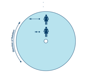
Figure 1. How the Coriolis force works
Materials of MEMS gyroscope
The material used in MEMS technology is mainly silicon, but thin films made of other materials are also used, such as germanium and gallium arsenide. MEMS gyroscopes mainly use the following types of materials:
1. Non-metals: silicon, germanium and gallium arsenide
2. Metals: Nickel and Aluminum
3. Polymer: SU8 and polyamide
4. Ceramics: diamond, SiC, SiO2, Si3N4.
There are three properties that need to be focused on during the MEMS gyroscope production process: elastic, inelastic and strength properties. At the same time, general attention should be paid to some properties, such as dielectric strength, resistivity, thermal conductivity, thermal expansion coefficient, etc.
Elastic properties
Elastic properties are mainly determined by two parameters: Young's modulus and Poisson's ratio. Young's modulus represents the stiffness of a material, while Poisson's ratio demonstrates the expansion of a material in a direction perpendicular to the direction of compression. Both parameters can be measured using load deflection techniques.
Inelastic properties
Plastic deformation occurs when a material deforms under stress without returning to its original shape. Therefore, it is very important to study the behavior of MEMS materials during inelastic deformation. Fatigue is also an important characteristic because it demonstrates how a MEMS device performs under constant stress or multiple stress cycles. Fatigue characteristics can lead to plastic deformation, which can lead to failure or performance degradation of MEMS devices.
Strength properties
There are several key strength-related properties to consider in MEMS gyroscope technology, such as tensile strength, fracture strength, flexural strength, and yield strength. These characteristics demonstrate the reliability and robustness of MEMS devices. Optimizing and improving these properties can be enhanced by improving the geometric design.
Due to the difficult conditions for micro-machining of MEMS materials, only a few materials can meet the requirements of the above three characteristics. The following table will compare and display the performance of different MEMS materials.
| Material | Elastic Modulus (GPa) | Failure strength (GPa) | Thermal Conductivity (W/cm/°C) | Coefficient of thermal expansion
(10-6 / °C) |
Specific heat capacity
(J/kg/k) |
Density
(kg/m3) |
Fracture toughness(Mpa.m1/2) |
| Diamond | 800 | 8.5 | 6.9 | 6.9 | 518 | 3500 | 5.9 |
| 3H-SiC | 400 | 7 | 3.5 | 3.3 | 1340 | 3200 | 3.8 |
| Si3N4 | 250 | 6.4 | 0.19 | 0.8 | 170 | 3100 | 1.8 |
| SiO2 | 70 | 1 | 0.001 | 0.55 | 937 | 2500 | 0.8 |
| SCSi (100) | 130 | 3.4 | 1.57 | 2.33 | 706 | 2300 | 1 |
| SCSi (110) | 168 | 7 | 1.57 | 2.33 | 706 | 2300 | 1 |
| Poly-Si | 159 | 1.65 | 0.34 | 2.8 | 706 | 2300 | 1.2 |
| Tungsten | 410 | 0.7 | 1.78 | 4.5 | 135 | 19300 | 44 |
| Aluminium | 70 | 0.17 | 2.36 | 25 | 899 | 2700 | 20 |
| Nickel | 185 | 0.4 | 0.899 | 13 | 444 | 8910 | 95 |
| Copper | 120 | 0.25 | 3.98 | 16.6 | 386 | 8960 | 85 |
| Titanium | 110 | 0.5 | 0.2 | 8.5 | 522 | 4510 | 70 |
| SU8 | 3 | 0.04 | 0.002 | 52 | NA | 1164 | NA |
| Polyimide | 8 | 0.04 | 0.001 | 20 | 1100 | 1420 | 3.9 |
| PVDF | 2.3 | 0.05 | 0.002 | 140 | 1500 | 1780 | 3.2 |
| PMMA | 2.4 | 0.08 | 0.002 | 80 | 1466 | 1200 | NA |
Table 1. Performance comparison of thin film materials used in MEMS
Structure of MEMS gyroscope
MEMS gyroscopes use the principle of sensing angular velocity of vibrating objects and use vibrations to induce and detect the Coriolis force. Therefore, MEMS gyroscopes have no rotating parts, no bearings, and can be mass-produced using micromachining technology. Most MEMS gyros rely on alternating Coriolis forces caused by mutually orthogonal vibrations and rotations, with the vibrating object suspended from a substrate by a soft elastic structure. The overall dynamic system is a two-dimensional elastic damping system in which vibration- and rotation-induced Coriolis forces transfer energy proportional to the angular velocity to the sensing mode.
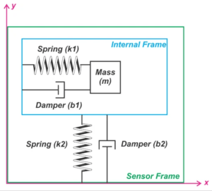
Figure 2. Structure of MEMS gyro
As can be seen in Figure 2, the mass (m) is connected to the "inner frame" through the damping spring structure (k1). In addition, an actuator controlled by a positive feedback system is used to drive the mass to undergo simple harmonic vibration. The feedback system ensures that the mass maintains a regulated, continuous oscillation along the x-axis. Furthermore, the inner frame is connected to the "sensor frame" via a second damping spring structure (k2) at 90° to the direction of mass oscillation. This configuration allows the inner frame to move in the y-axis direction when a force is present in that direction.
Angular velocity can be detected when a MEMS gyroscope rotates about an axis perpendicular to the XY plane shown in the figure. Figure 3 shows the process of counterclockwise rotation of the gyroscope on a fixed platform. This image shows the gyroscope at two different times. Although the distance of the sensor from the center of the platform is fixed, we know that the mass distance changes from r1 to r2 due to its oscillation in the x-direction of the sensor frame. In this example, the mass distance increases by r2 > r1. Based on this principle and structure, Ericco has designed MEMS gyros suitable for use in many fields, such as the ER-MG2-50/100 suitable for ground navigation, whose bias instability can reach 0.01-0.02°/hr bias instability. The ER-MG2-300/400 is used for air and maritime navigation, and the deviation instability can reach 0.03-0.05° deg/hr.
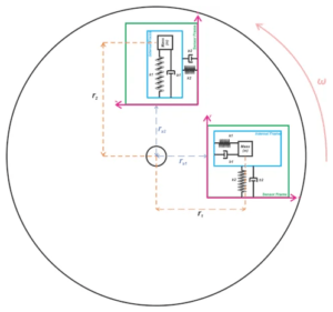
Figure 3. Gyroscope rotating counterclockwise on a fixed platform
I hope that by reading this article, you can understand the materials and structure of MEMS gyroscope. If you want to know more about MEMS, please read the related articles and related products below.
More Technical Questions
1.What’s the advantages and disadvantages of MEMS gyroscope?
2.Basic Knowledge of Bias Stability of MEMS Gyroscope
3.MEMS gyroscope VS FOG: What’s the difference between them?
4.Comparison Of Technical Specifications Of Navigation Grade MEMS Gyroscope
5.MEMS Gyroscope: The Third Generation Of Gyroscopes Is Leading The Way
6.MEMS Gyroscope: Sensitive Structure | Detection Circuit | Integrated Package
Products in Article


 High Performance Navigation Grade MEMS Gyroscope
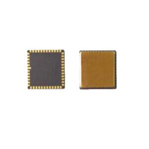
.jpg)