


)
&description=&image=https://www.ericcointernational.com/wp-content/uploads/2025/06/19-1024x1024.png)
MEMS Gyroscopic Directional Module for Gyro Tools (Direct Replacement for Fluxgate Module)
Introduction
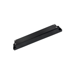
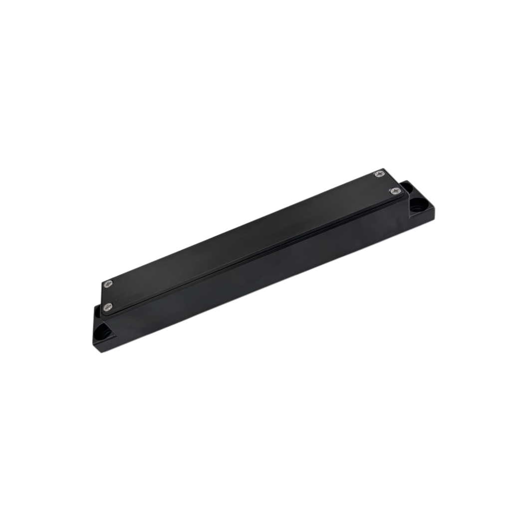
The ER-Gyro-19 is a revolutionary MEMS-based gyro directional module designed for direct, drop-in replacement of standard fluxgate modules. With fully compatible electrical interfaces and mechanical dimensions, it integrates seamlessly into existing probe and logging tool architectures—eliminating hardware redesign costs.
Utilizing strapdown inertial measurement technology by 3-axis navigation-grade MEMS gyro and 3-axis MEMS accelerometer, it delivers reliable azimuth, inclination, and tool face data. This module is unaffected by magnetic interference—ensuring accuracy where traditional magnetic tools fail.
Core Advantages
- Pioneering High Accuracy in Small Inclination:Delivers effective azimuth and tool face precision even at small well inclinations, maintaining accuracy within 3°.
- Designed for Harsh Conditions:Features the most advanced MEMS technology and an all-solid-state design with superior shock and vibration resistance, performing reliably under intense random vibrations.
- Rapid & Precise Alignment:Achieves 1° azimuth accuracy in just 30 seconds, and 0.5° accuracy within 90 seconds, maximizing operational efficiency.
- Extreme Environmental Suitability:Fully calibrated and compensated across a wide temperature range of 5°C to 125°C.
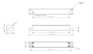
- Ultra-Compact Form Factor:Dimension136.8mm x 20.3mm x 19mm. . Replaces fluxgate sensors in situ with no system modifications, offering an immediate and cost-effective path to non-magnetic measurement capability.
Applications
- Oil & Gas Drilling & Logging:for Measurement-While-Drilling (MWD)/Logging-While-Drilling (LWD) in cased holes, side-tracks, and wells with significant magnetic interference from drill strings, casings, or geological formations.
- Cased-Hole Logging & Well Intervention:for gyroscopic surveys in production wells and for providing precise directional data for well abandonment, sidetracking, and re-entry operations where magnetic tools are unusable.
- Pipeline & Utility Installation (HDD):for the accurate mapping of pipeline routes, especially in congested urban areas with existing underground utilities that create magnetic noise.
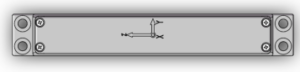
Figure 1. X,Y,Z Coordinate Definition of the ER-Gyro-19 (top view)
Performance parameters
| Model | ER-Gyro-19A | ER-Gyro-19B | ER-Gyro-19H |
| Azimuth accuracy(1σ,°secψ) | 1 | 0.5 | 1 |
| Gyro tool face angle accuracy(°,1σ) | 1/secL
(L stands for latitude) |
1/secL
(L stands for latitude) |
|
| Well inclination alignment accuracy (°,1σ) | 0.1 | 0.1 | |
| Alignment Time | 30 seconds (90 seconds optional) | 30 seconds (90 seconds optional) | |
| Azimuth precision retention time | 20min | 20min | |
| Attitude precision retention time | 20min | 20min | |
| Azimuth measurement range(°) | 0~360 | 0~360 | |
| Gravity tool face angle measurement range(°) | -180~180 | -180~180 | |
| Gyro tool face angle measurement range(°) | 0~360° | 0~360° | |
| Well inclination measurement range(°) | 0~180 | 0~180 | |
| Update rate (Hz) | 100 | 100 | |
| Power supply and working environment | |||
| Operating temperature(℃) | 5~+85 | 5~125 | |
| Storage temperature (℃) | 0~+90 | 0~130 | |
| Wide voltage (V) | 6~12V | 6~12V | |
| Power (W) | 2 | 3 | |
| Communication interface | RS-422 | RS-422 | |
| Appearance characteristics | |||
| Size (mm×mm) | 136.8mm x 20.3mm x 19mm | ||
| Weight (g) | ≤150g | ||
Wiring Definition
| Connector Model | Pinout | Definition |
| J30J-15ZKP | 1 | +6~12V |
| 3 | GND | |
| 6 | Tx+ | |
| 7 | Tx- | |
| 8 | Rx+ | |
| 9 | Rx- | |
| 10 | GND |
Dimension
Communication protocol
- Data output protocol
| Byte | Content | Note | Data type |
| 1 | EB | Protocol header | Unsigned char |
| 2 | 80 | Protocol header | Unsigned char |
| 3 | 55 | Protocol header | Unsigned char |
| 4 | AA | Protocol header | Unsigned char |
| 5~8 | Sensor Data | X Gyroscope, deg/s | float |
| 9~12 | Sensor Data | Y Gyroscope, deg/s | float |
| 13~16 | Sensor Data | Z Gyroscope, deg/s | float |
| 17~20 | Sensor Data | X Accelerometer, m/s^2 | float |
| 21~24 | Sensor Data | Y Accelerometer, m/s^2 | float |
| 25~28 | Sensor Data | Z Accelerometer, m/s^2 | float |
| 29 | System State | 0 alignment 1 navigation | Unsigned char |
| 30~33 | System Results | Azimuth | float |
| 34~37 | System Results | Inclination | float |
| 38~41 | System Results | tf_gravity | float |
| 42~45 | System Results | tf_gyro | float |
| 46~49 | System Results | Temperature | float |
| 50 | Counter | Frame count | Unsigned char |
| 51 | Checksums | 1~50 Bytes sum | Unsigned char |
- Data input protocol
| Byte | Content | Note | Data type |
| 1 | AA | Protocol header | Unsigned char |
| 2 | 15 | Protocol header | Unsigned char |
| 3 | AA | Protocol header | Unsigned char |
| 4 | 15 | Protocol header | Unsigned char |
| 5~8 | Lon | Degree | float |
| 9~12 | Lat | Degree | float |
| 13~16 | Alt | Meter | float |
| 17~20 | G0 | Gravitational acceleration | float |
| 21~22 | Time | Alignment Time | short |
| 23 | AA | Protocol End | Unsigned char |
| 24 | BB | Protocol End | Unsigned char |
| 25 | CC | Protocol End | Unsigned char |
| 26 | DD | Protocol End | Unsigned char |
Application Techniques
1.MEMS Gyro Directional Module fully upgraded,Redefined measurement standards
2.How can MEMS directional module achieve precise targeting?
3.ER-Gyro-15: MEMS Directional Sensor that Redefines Downhole Exploration Accuracy
4.MEMS Gyroscope Directional Module for GWD: New solutions for well logging
5.MEMS Directional Sensor Newly Released: an Innovative Tool for Oil Drilling Technology
6.Accurate Directional Attitude Measurement Helps Revolutionize Underground Engineering!
More Products
 MEMS Gyroscopic Directional
Module for Gyro Tools
 Quick MEMS North Seeker for Heading Machine
 Dynamic MEMS north Seeker for Heading Machine
 Low Cost MEMS North Seeker for Heading Machine
 High Accuracy Single-Axis MEMS Gyro
 MEMS Directional Module For Mining Well-Trajectory Measurement Device