


ER-Gyro-15 MEMS Gyroscopic Directional Module for Gyro Tools
Introduction
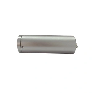
The ER-Gyro-15 is a compact, high-performance MEMS gyroscopic directional module designed for demanding downhole environments. Utilizing strapdown inertial measurement technology by 3-axis navigation-grade MEMS gyro and 3-axis MEMS accelerometer, it delivers reliable azimuth, inclination, and tool face data. This module is unaffected by magnetic interference—ensuring accuracy where traditional magnetic tools fail
Core Advantages
- Pioneering High Accuracy in Small Inclination:Delivers effective azimuth and tool face precision even at small well inclinations, maintaining accuracy within 3°.
- Designed for Harsh Conditions:Features the most advanced MEMS technology and an all-solid-state design with superior shock and vibration resistance, for unstable factors such as shaking or vibration that occur in the actual working environment underground, it can work
- Extreme Environmental Suitability:Fully calibrated and compensated across a wide temperature range of 5°C to 125°C.
- Ultra-Compact Form Factor:Revolutionary miniaturization (ø30mm/ø25.4mm/ø6mm) allows seamless integration into narrow probe spaces, unlike bulky traditional gyro tools.
Applications
- Oil & Gas Drilling & Logging:for MWD/LWD in casing, tubing, or magnetically disturbed well sections.
- Advanced Mining & Tunneling:Provides essential pointing for directional drilling equipment used in mineral exploration, seam tracking, and underground development. Its non-magnetic nature ensures reliability near heavy machinery and steel infrastructure.
- Pipeline & Utility Installation & Inspection:Critical for the accurate mapping of pipeline routes, especially in complex directional drilling (HDD) projects.
- Geotechnical & Environmental Surveying:borehole trajectory measurement for geotechnical investigation, environmental monitoring well installation, and other subsurface surveying needs where magnetic interference is a concern.
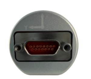
Figure 1. X,Y,Z Coordinate Definition of ER-Gyro-15 (front view)
Specifications
| Model | ER-Gyro-15A | ER-Gyro-15B | ER-Gyro-15H |
| Azimuth accuracy(1σ,°secψ) | 1 | 0.5 | 1 |
| Gyro tool face angle accuracy(°,1σ) | 1/secL
(L stands for latitude) |
1/secL
(L stands for latitude) |
|
| Well inclination alignment accuracy(°,1σ) | 0.1 | 0.1 | |
| Alignment Time | 180 seconds | 180 seconds | |
| Azimuth precision retention time | 20min | 20min | |
| Attitude precision retention time | 20min | 20min | |
| Azimuth measurement range(°) | 0~360 | 0~360 | |
| Gravity tool face angle measurement range(°) | -180~180 | -180~180 | |
| Gyro tool face angle measurement range(°) | 0~360° | 0~360° | |
| Well inclination measurement range(°) | 0~180 | 0~180 | |
| Update rate (Hz) | 100 | 100 | |
| Power supply and working environment | |||
| Operating temperature(℃) | 5~+85 | 5~125 | |
| Storage temperature(℃) | 0~+90 | 0~130 | |
| Wide voltage(V) | 6~12V | 6~12V | |
| Power(W) | 2 | 3 | |
| Communication interface | RS-422 | RS-422 | |
| Appearance characteristics | |||
| Size(mm×mm) | Option A: Φ30mm x 120mm
Option B: Φ25.4mm x 120mm Option C: Φ18.6mm x 120mm |
||
| Weight(g) | ≤150g | ||
Wiring Definition
| Connect Type | Pin | Definition |
| J30J-15ZKP | 1 | +6~12V |
| 3 | GND | |
| 6 | Tx+ | |
| 7 | Tx- | |
| 8 | Rx+ | |
| 9 | Rx- | |
| 10 | GND |
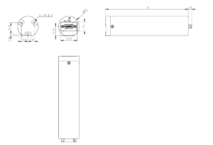
Dimension
Communication protocol
- Data output protocol
| Byte | Content | Note | Data type |
| 1 | AA | Protocol header | Unsigned char |
| 2 | 15 | Protocol header | Unsigned char |
| 3 | AA | Protocol header | Unsigned char |
| 4 | 15 | Protocol header | Unsigned char |
| 5~8 | Lon | Degree | float |
| 9~12 | Lat | Degree | float |
| 13~16 | Alt | Meter | float |
| 17~20 | G0 | Gravitational acceleration | float |
| 21~22 | Time | Alignment Time | short |
| 23 | AA | Protocol End | Unsigned char |
| 24 | BB | Protocol End | Unsigned char |
| 25 | CC | Protocol End | Unsigned char |
| 26 | DD | Protocol End | Unsigned char |
- Data input protocol
| Byte | Content | Note | Data type |
| 1 | AA | Protocol header | Unsigned char |
| 2 | 15 | Protocol header | Unsigned char |
| 3 | AA | Protocol header | Unsigned char |
| 4 | 15 | Protocol header | Unsigned char |
| 5~8 | Lon | Degree | float |
| 9~12 | Lat | Degree | float |
| 13~16 | Alt | Meter | float |
| 17~20 | G0 | Gravitational acceleration | float |
| 21~22 | Time | Alignment Time | short |
| 23 | AA | Protocol End | Unsigned char |
| 24 | BB | Protocol End | Unsigned char |
| 25 | CC | Protocol End | Unsigned char |
| 26 | DD | Protocol End | Unsigned char |
Application Techniques
1.MEMS Gyro Directional Module fully upgraded,Redefined measurement standards
2.How can MEMS directional module achieve precise targeting?
3.ER-Gyro-15: MEMS Directional Sensor that Redefines Downhole Exploration Accuracy
4.MEMS Gyroscope Directional Module for GWD: New solutions for well logging
5.MEMS Directional Sensor Newly Released: an Innovative Tool for Oil Drilling Technology
6.Accurate Directional Attitude Measurement Helps Revolutionize Underground Engineering!
More Products
 MEMS Gyroscopic Directional Module for Gyro Tools(Direct Replacement for Fluxgate Module)
 Quick MEMS North Seeker for Heading Machine
 Dynamic MEMS north Seeker for Heading Machine
 Low Cost MEMS North Seeker for Heading Machine
 High Accuracy Single-Axis MEMS Gyro
 MEMS Directional Module For Mining Well-Trajectory Measurement Device