


ER-MNS-09 MEMS Directional Module For Mining Well-Trajectory Measurement Device
Introduction
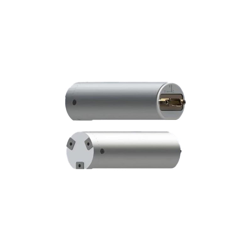
The ER-MNS-09 is a MEMS gyroscopic directional module for well trajectory measurement device with a special-shaped cylindrical design. It uses high-precision MEMS gyroscope that can find the north by itself. It determines the geographic true north direction by measuring the earth's rotation component. It does not rely on the geomagnetic field and can work stably in underground mines, metal pipelines or strong electromagnetic environments
It can realize azimuth measurement, real-time output of carrier attitude reference value and attitude holding function. It has strong anti-impact and vibration ability, small size, light weight and low power consumption, and is the most ideal equipment in the fields of mining, geophysical exploration, directional drilling, etc.
Features
- Revolutionary miniaturization (ø30mm/ø25.4mm/ø18.6mm) allows seamless integration into narrow probe spaces;
- Adopt the latest three-axis MEMS gyro, three-axis MEMSaccelerometer strapdown inertial measurement technology;
- Full solid-state design, built-in inner platform, excellent impact and vibration resistance, and resistant to harsh environments;
- 4. With self-seeking north function, not affected by magnetic field;
Applications
1.Orientation and attitude measurement of advanced mining/drilling equipment;
2.Direction and trajectory control of non-excavation underground hidden engineering pipeline tracking and mapping;
3.Pipeline laying through and across operations in HDD;
4.Provide reference direction for total station and pointing instrument in tunnel construction;
5.Find north positioning in land surveying/land mobile mapping system.
")
Figure 1. ER-MNS-09 coordinate axis definition (front view)
Specifications
| Model | ER-MNS-09A | ER-MNS-09B | ER-MNS-09HA | ER-MNS-09HB |
| Azimuth accuracy(1σ, °secψ) | 1 | 0.5 | 1 | 0.5 |
| Attitude accuracy(1σ, °) | ≤0.2 | |||
| Azimuth accuracy retaining time | 20min | |||
| Attitude accuracy retaining time | 20min | |||
| Azimuth measurement range(°) | 0~360 | |||
| Inclination measurement range(°) | -85~85 | |||
| North-seeking time | 3min | |||
| North-seeking method | stationary | |||
| Update rate (Hz) | 100 | |||
| Power supply and working environment | ||||
| Operating temperature(℃) | 5~+55 | 5~+125 | ||
| Storage temperature(℃) | 0~+65 | 0~+130 | ||
| Wide voltage (V) | 6~12V | |||
| Power(W) | 3 | |||
| Communication interface | RS-422 | |||
| Appearance characteristics | ||||
| Size (mm×mm) | Option A: Φ30mm x 120mm
Option B: Φ25.4mm x 120mm Option C: Φ18.6mm x 120mm |
|||
| Weight(g) | ≤150g | |||
Wiring Definition
| Connect Type | Pin | Definition |
| J30J-15ZKP | 1 | 6~12V |
| 3 | GND | |
| 6 | Tx+ | |
| 7 | Tx- | |
| 8 | Rx+ | |
| 9 | Rx- |
Dimension

Data protocols
Upper computer receiving protocol
The data update rate is 100Hz, the baud rate is 230400bps, and each frame contains 61 bytes of data, each byte contains 1 start bit (0), 8 data bits, 1 stop bit (1), and no parity. The specific data format is shown in the table below:
Table 1 Receive data frame format
| Bytes (60 bytes total) | Data content | supplementary note |
| 1~4 | header | EB8055AA |
| 5~8 | X Gyro Data | Low then high, dimensionless digital FLOAT |
| 9~12 | Y gyro data | Low then high, dimensionless digital FLOAT |
| 13~16 | Z Gyro Data | Low then high, dimensionless digital FLOAT |
| 17~20 | X ACCL data | Low then high, dimensionless digital FLOAT |
| 21~24 | Y ACCL data | Low then high, dimensionless digital FLOAT |
| 25~28 | Z ACCL data | Low then high, dimensionless digital FLOAT |
| 29~32 | Lon | Low then high, 0.000001°. |
| 33~36 | Lat | Low then high, 0.000001°. |
| 37~40 | Alt | First low, then high, 0.000001m |
| 41~44 | register | Low then high, 10ms |
| 45~46 | PIT | Low then high, 0.01° |
| 47~48 | ROL | Low then high, 0.01° |
| 49~50 | YAW | Low then high, 0.01° |
| 51~52 | V_n | First low then high, 0.01m/s |
| 53~54 | V_u | First low then high, 0.01m/s |
| 55~56 | V_e | First low then high, 0.01m/s |
| 57 | state of affairs | 0xA1 alignment, 0xB1 hold |
| 58 | end of frame | 0x00 |
| 59 | end of frame | 0xFF |
| 60 | end of frame | 0x34 |
| 61 | matching test | EB 80 and the sum of all bytes other than itself |
Host computer sending protocol
Total number of bytes sent down in a single transmission: 21 bytes, baud rate 230400bps, no parity, each byte includes: start bit (0), data bit (8 bits), stop bit (1).
- priming
| byte symbol | define | note |
| 1 | 0xEB | |
| 2 | 0x80 | |
| 3 | 0x00 | |
| 4 | 0xCC | |
| 5-8 | 0x00 | |
| 9-12 | 0x00 | |
| 13-16 | 0x00 | |
| 17-21 | 0x00 |
- Send warp and woof height
| byte symbol | define | note |
| 1 | 0xEB | |
| 2 | 0x80 | |
| 3 | 0x00 | |
| 4 | 0xAA | |
| 5-8 | Latitude | |
| 9-12 | longitudes | |
| 13-16 | Altitude | |
| 17 | 0xAA | |
| 18 | 0xBB | |
| 19 | 0xCC | |
| 20 | 0xDD | |
| 21 | 5~20 heterodyne calibration |
Determine the definition of the data sent based on byte 4:
- if control_flag==0xCC: restart work
- if control_flag==0xAA: send latitude/longitude altitude
Send order: 5-8 bytes: latitude (*1e6 in °)
9-12 bytes: longitude (*1e6 in °)
13-16 bytes: altitude (*1 in m)
For example, the C code that sends the latitude/longitude instruction (the rest of the bytes are configured arbitrarily), Latitude is "latitude * 1e6", longitude is similar, and altitude scale is 1.
bytSend[0] = 0xeb;
bytSend[1] = 0x80;
bytSend[2] = 0x00;
bytSend[3] = 0xaa;
bytSend[4] = (Latitude>>24) & 0xff;
bytSend[5] = (Latitude>>16) & 0xff;
bytSend[6] = (Latitude>>8) & 0xff;
bytSend[7] = (Latitude) & 0xff.
bytSend[8] = (Longitude>>24) & 0xff;
bytSend[9] = (Longitude>>16) & 0xff;
bytSend[10] = (Longitude>>8) & 0xff;
bytSend[11] = (Longitude) & 0xff.
bytSend[12] = (altitude>>24) & 0xff;
bytSend[13] = (altitude>>16) & 0xff;
bytSend[14] = (altitude>>8) & 0xff;
bytSend[15] = (altitude) & 0xff;
bytSend[16] = 0xaa;
bytSend[17] = 0xbb;
bytSend[18] = 0xcc;
bytSend[19] = 0xdd;
bytSend[20] = b[4]^b[5]^... .b[19];
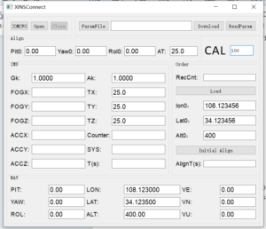
Introduction to the software
Click the COMCFG button to set the serial port, baud rate and frequency. The baud rate is 230400 and the frequency CAL is 100HZ.
Click Open to start the test.
Click Initial Align to start the north search, the search time is 300s.The result is displayed at PIT;YAW;ROL.
If you want to change the latitude and longitude, please change them at Lon0 and Lat0, then click Load, and then click Initial Align to re-navigate.
Application Techniques
1.MEMS Gyro Directional Module fully upgraded,Redefined measurement standards
2.How can MEMS directional module achieve precise targeting?
3.ER-Gyro-15: MEMS Directional Sensor that Redefines Downhole Exploration Accuracy
4.MEMS Gyroscope Directional Module for GWD: New solutions for well logging
5.MEMS Directional Sensor Newly Released: an Innovative Tool for Oil Drilling Technology
6.Accurate Directional Attitude Measurement Helps Revolutionize Underground Engineering!
More Products
 MEMS Gyro Tools Directional Module(Can replace fluxgate directional module)
 Quick MEMS North Seeker for Heading Machine
 Dynamic MEMS north Seeker for Heading Machine
 Low Cost MEMS North Seeker for Heading Machine
 High Accuracy Single-Axis MEMS Gyro
 MEMS Gyro Tools Directional Module