The strap-down north finder’s inertial measurement unit consists of a fiber optic gyroscope and an accelerometer, which are used to measure the earth's rotation angular velocity and gravity acceleration components respectively, thereby determining the azimuth angle and attitude angle of the carrier.
During the use of the strap-down north finder, the angular velocity of the interference to the gyro must also be a small amount. However, in the actual use of the north finder, it will be affected by high-frequency interference caused by vehicle engines, low-frequency interference caused by gusts of wind, near-constant interference caused by foundation settlement, and interference from vibrations such as people walking and passing vehicles. The magnitude of these angular velocity interference ranges from 1°/h to 10°/h, which is much larger than the allowable error of 0.01°/h. Therefore, some measure must be taken to separate the angular velocity interference from the gyro output. The low-pass filtering method is usually used to filter out the influence of interference signals. Experiments have shown that this method is effective in some cases. However, when the spectrum of the useful signal and the interference signal overlap significantly, the filtering effect is not obvious, and the north-finding accuracy cannot meet the target. requirements, in addition to establishing a dynamic model of the system, the Kalman filter method can also improve the system accuracy. However, it is difficult to establish a dynamic model of the interference signal. This method has great difficulties in application. This article uses measuring the size of the angular velocity interference to Improve north seeking accuracy.
1.Calculation principle of north finder
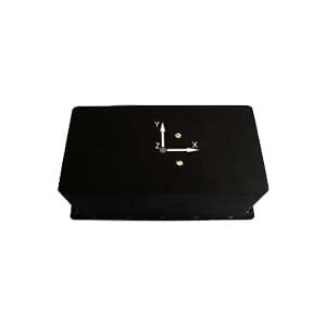
Under ideal conditions, north finder is used to measure the azimuth angle between the carrier's longitudinal axis and the geographical north direction and the attitude angle between the carrier and the geographical horizontal plane. In the north-finder, both the gyroscope and the accelerometer are installed on a platform that can rotate back and forth within 180°; the H-axis of the gyroscope is vertically upward, and the two sensitive axes of the accelerometer are parallel to the two sensitive axes of the gyroscope,perpendicular to the stepper motor's axis of rotation.
The relationship between the geographical coordinate system and the carrier coordinate system is shown in Figure 1. The carrier coordinate system is represented by xb, yb, zb, which is defined according to the right-hand coordinate system. The yb axis is defined as the carrier longitudinal axis, and the z b axis is vertically upward. The geographical coordinate system is selected as the northeast sky coordinate system, represented by xn, yn, and zn. Among them, K, α and β represent the azimuth angle, pitch angle and roll angle respectively. According to the relationship between the carrier coordinate system and the geographical coordinate system, the projections of the earth's rotation angular velocity and gravity acceleration on the carrier coordinate system xb and yb can be obtained as:
 If the output signals of the two axes of the gyroscope are the true components of the earth's rotation angular velocity sensed by the carrier, the north-finding solution formula is:
 However, in the actual solution process, the measurement output of the gyroscope contains angular velocity interference, so its existence will affect the north-finding accuracy.
2.Measurement principle of interference angular velocity
When the carrier is disturbed by angular motion, on the one hand, the attitude angle will change, causing the projection of gravity acceleration on the carrier coordinate system to change, thus causing the output of the accelerometer to change. On the other hand, the angular rate of angular motion interference is sensed by the gyroscope, and its integration can obtain the change in attitude angle. In this way, by comparing the attitude angles calculated by integrating the accelerometer output and the gyroscope output respectively, and performing appropriate feedback control, it is possible to separate the disturbing angular rate from the gyroscope output.
This method first constructs a v coordinate system. The angle relationship between the v coordinate system and the carrier coordinate system is represented by the attitude matrix, which is completely determined by the pitch angle α and the roll angle β. From this, we can get: The measurement principle block diagram of interference angular velocity is shown in the figure.
 Since the output of the gyroscope also contains the component of the earth's rotation angular velocity, the gyroscope output needs to be corrected to offset the influence of the earth's rotation angular velocity component. To this end, the output of the accelerometer can be involved in the real-time solution process of the attitude matrix. It can be assumed that the accelerometer has no measurement error, and its output can truly reflect the projection of gravity acceleration on the attitude coordinate system. Through the combined calculation of gyroscope and accelerometer, the mathematical platform can be precisely leveled and the accurate value of the projection on the earth's rotation angular velocity plane can be obtained.
3.Summary
This paper uses the output signals of gyroscopes and accelerometers to measure interference signals, achieves separation of useful signals and interference signals, and improves the anti-interference ability of the strap-down north seeker. This method does not rely on any auxiliary tools or complex filtering methods. Based on a deep understanding of the principle of the strap-down north seeker, it uses the inertial measurement device of the strap-down north finder itself to achieve real-time compensation. Ericco currently has quite mature technology in anti-interference for north seekers. If you are interested, you can learn about our fiber optic north seekers and MEMS north seekers.
More Technical Questions
1.Analysis and Calibration of North Seeker Transposition Error
2.Analyze the Software Design of North Finder
3.Technical Analysis of FOG North Finder in Improving Accuracy
4.Research on Signal Acquisition of Strap-down North Seeker
5.Error Analysis and Compensation Technology of North Seeker
6.Introduction and features of MEMS north seeker
Products in Article