MEMS-IMU is a micro-electromechanical inertial measurement unit, which has the following advantages: small size, light weight, solid structure, low power consumption, fast startup, low cost, high reliability, good maintainability, and strong environmental adaptability. Due to the integral operation characteristics of the inertial navigation system, even small inertial device measurement errors will cause the accumulation of inertial navigation attitude, speed and position calculation errors over time. Therefore, it is of great significance to improve the actual accuracy of existing inertial devices through testing and error compensation. This article will introduce the IMU calibration method, MEMS IMU error modeling, MEMS-IMU system error calibration steps and vision-based online MEMS-IMU error compensation.
IMU calibration method
Calibration of traditional IMUs is usually accomplished by a special precision turntable. Calibration is usually accomplished by using a mechanical turntable to control the IMU at a known rotational angular velocity according to a set of precisely controlled postures. The calibration method based on the turntable is simple and highly accurate. However, the devices used for calibration are usually very expensive. For low-cost MEMS-IMUs, the cost of using a precision turntable for calibration even exceeds the cost of the IMU hardware, and it is often not necessary to use such a method. High-precision calibration method.
For the static error of the IMU, there is a robust and convenient method to calibrate the IMU that does not rely on external equipment. However, this method only corrects the systematic errors of the IMU, including static zero bias, scaling factors and inter-axis non-orthogonal errors. It does not model and analyze the random errors of the IMU. The Allan variance analysis method can also be used to analyze the random errors of the IMU. Perform analysis. Allan variance analysis is a static error, and IMU data must be collected under a static base. In practical applications of IMU, the motion characteristics of the base need to be integrated. In addition, the IMU is affected by bias repeatability and operating temperature. Only online compensation can meet the requirements of navigation accuracy and real-time performance.
There is a vision-based IMU error online correction method that uses IMU pre-integration and fuses the IMU with the visual sensor through Kalman filtering to achieve online estimation of the IMU bias. The combined system of IMU and visual sensor is a nonlinear system. The extended Kalman filter performs a Taylor expansion at a fixed point, which introduces nonlinear errors and permanently discards the old state information. In comparison, the nonlinear optimization method After each iteration, when the state estimate changes, Taylor expansion is performed on the new estimated point to further reduce the error.
MEMS-IMU error modeling
The errors of MEMS-IMU can be divided into systematic errors and random errors. System errors can be eliminated through sensor calibration. Random errors can be intuitively understood as the degree of fluctuation and drift of the zero bias. It is usually assumed that the zero bias noise of low-cost MEMS-IMUs obeys Gaussian distribution. IMU errors include gyroscope errors and accelerometer errors. The error characteristics of gyroscopes and accelerometers are similar. Compared with accelerometers, gyroscopes also include errors caused by acceleration.
The angular velocity and acceleration measurement model applied to low-cost MEMS-IMU can be expressed as:
![]() (1)
(1)
The random errors of IMU usually include quantization noise, angle (velocity) random walk, angular rate (acceleration) random walk, bias instability, rate slope and bias repeatability, etc. When analyzing the random error of low-cost MEMS-IMU, it is difficult to obtain each of the above typical error coefficients. It is generally believed that the random error only includes random walk error and bias instability. The ng and na in Equation (1) are It is considered to be a Gaussian white noise term, consisting of a random walk error and a part of the bias instability error. ba and bg are Wiener processes, consisting of another part of the bias instability, and satisfy:
![]() (2)
(2)
That is, nba and nbω in equation (2) satisfy Gaussian distribution.
MEMS-IMU system error calibration
Assuming that on a carrier equipped with an IMU, the non-orthogonal error between the axes of the ideal orthogonal coordinate system is caused by the packaging error of the three-axis accelerometer coordinate system and the gyroscope coordinate system and the axis-to-axis alignment error.
In the calibration method based on the turntable, the coordinate system of the IMU is specified to coincide with the coordinate system of the turntable, so that the input of the turntable can become the true value measured by the IMU. When a turntable is not used for calibration, the coordinate system can be artificially specified, and based on this, the error model can be simplified. Let the axis of the coordinate system coincide with the axis of the accelerometer, and XbOYb
Coplanar with XaOYa. Under this assumption, the inter-axis non-orthogonal error of the accelerometer is simplified to:
 (3)
(3)
In order to calibrate the accelerometer non-alignment error, it is necessary to estimate the parameter vector shown in equation (4).
![]() (4)
(4)
For MEMS-IMU, steps to collect data required for calibration
include:
1) Keep the IMU horizontally stationary for more than 50 seconds;
2) Rotate the IMU to a different position;
3) Still for at least 1 s;
4) Continue steps 2) 3) more than 50 times.
Random error coefficient analysis based on Allan variance
The physical meaning and application essence of Allan variance comes from its relationship with the power spectrum. The Allan variance method is a time domain analysis technique.
Using this technique, the inertial device data collected under actual static conditions are analyzed to obtain a logarithmic curve chart. Different error coefficients can be identified based on the slopes of different fitting straight lines. The method of calibrating the MEMS-IMU error model using Allan variance can be summarized as follows:
1) Keep the IMU sensor stationary to acquire IMU data with a time length of Ω(t), the number of sampling points is N, and the sampling time is τ 0;
2) Divide the data into K groups and set the duration of each time period τ = Mτ 0, where M is the factor used for averaging, and M can be taken as any value that satisfies M ≤ ( N - 1) /2 value. Among them, consecutive data groups are separated by time τ 0. Taking the gyroscope as an example, ωi is the output of the gyroscope at sampling time i, then the data grouping situation is as follows:
 (5)
(5)
Sensor data is averaged over time. Taking the gyroscope as an example, methods based on angular rate measurements and angle measurements can be used. In the method based on angular rate measurements: the duration τ of each group is called the correlation time, and the average value of each group is calculated as follows:
 (6)
(6)
In this way, M corresponding variances at each averaging time will be obtained. According to the plot of these M points, a logarithmic curve of the Allan standard deviation changing with the average time can be obtained, that is, the Allan variance curve.
Vision-based online MEMS-IMU error compensation
Through Allan variance analysis, ideally, the quantization noise, angular random walk, angular rate random walk, bias instability noise, and rate slope of the device can be obtained. These are all analyzes of bias quality and can also be intuitively It is understood as the degree of fluctuation and drift of the zero bias, but the size of the zero bias itself is not analyzed, and this is the error that needs to be estimated when MEMS-IMU is actually used. Calibrating the system error can obtain a constant value of the deviation, but the zero offset is also affected by noise. In addition, the relevant calibration collects data under a static base. In practical applications, the MEMS-IMU needs to be collected under a moving base.
The data causes the MEMS-IMU to be affected by the motion characteristics of the base, and the IMU is affected by the bias repeatability and operating temperature every time it is powered on. Therefore, only online compensation can meet the navigation accuracy and real-time requirements of the MEMS-IMU.
Currently, based on the natural complementarity of visual sensors and IMUs, it has become the smallest sensor combination for sufficient self-awareness and environmental awareness. If the working environment is limited to static, rigid bodies, scenes with insignificant lighting changes and no human interference, without prior information about the environment, it is quite mature to establish a model of the environment during movement and estimate one's own movement at the same time. On the whole, vision and IMU sensors jointly realize the posture estimation of the carrier, and there is a certain complementarity. IMU is suitable for calculating short-term, fast movements; vision is suitable for calculating long-term, slow movements. Therefore, visual positioning information can be used to estimate the zero bias of the IMU and reduce the divergence and cumulative errors of the IMU caused by the zero bias. In practical applications, the IMU is modeled as:
 (7)
(7)
The schematic diagram based on vision and IMU fusion is shown in Figure 1.

Figure:Schematic diagram of visual inertia fusion
The integration of vision and IMU generally uses a sliding window method to construct an optimization problem:
Summarize
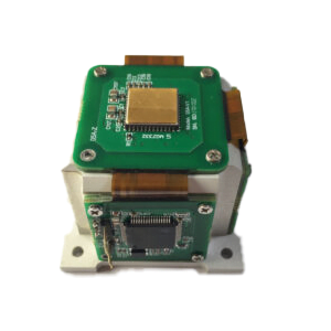
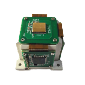
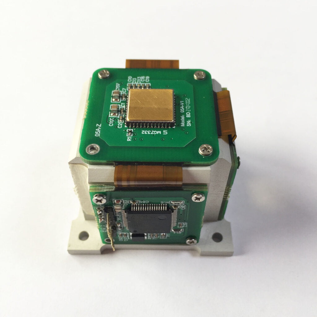
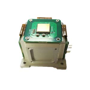
Low-cost MEMS-IMU has the advantages of small size, light weight, low cost, and high reliability, but its accuracy is relatively low. The method proposed in this article effectively improves the positioning accuracy of MEMS-IMU. When the error model of MEMSIMU is reasonably constructed, data can be collected through specific methods, and the error can be achieved using nonlinear optimization methods without relying on expensive test calibration equipment. Calibration of system error parameters in the model; By using the Allan variance analysis method, the angle (velocity) random walk coefficient and bias instability coefficient of the MEMS-IMU that are valuable for use can be obtained; Based on the above calibration analysis results, combined with the visual sensor, using The nonlinear optimization method can further estimate the deviation of the MEMS-IMU online in real time and compensate it to improve its actual use accuracy and achieve positioning. The disadvantage of this method is that it requires the use of visual sensors, which are greatly affected by the environment. The robustness of the algorithm needs to be further improved in the future. As an inertial navigation company, ERICCO studies MEMS IMUs. The self-developed MEMS IMUs have high performance, low cost and small size. For example, ER-MIMU-01 and ER-MIMU-02 can independently seek north, and the gyros inside have relatively high accuracy. Compared with many peer companies, the accuracy is much higher. If you want to buy an IMU, please contact us.
More Technical Questions
1.Application of Improved Wavelet De-noising Method in MEMS-IMU Signals
2.Research on error modulation technology of MEMS based on IMU rotation
3.Research on MEMS-IMU signal denoising technology
5.IMU self-calibration based on factorization
6.Influence analysis of IMU accuracy on spoofing detection algorithm
Products in Article