IMU is used to measure the angular velocity and acceleration of objects. The accuracy of the IMU determines the accuracy of its measurement data and has an important impact on the deception detection algorithm. Global navigation satellite system (GNSS)/inertial navigation system (INS) tightly integrated navigation system usually uses the original observation information (such as pseudorange, pseudorange rate, Doppler, etc.) output by GNSS as Measurements. INS is an inertial navigation system, a system that uses IMU measurement data for navigation. The optimal state estimator of the system is obtained through fusion filtering by the Kalman filter and the measurement values output by the inertial measurement unit in the INS. The tight combination mode has become a hot spot in the current research on GNSS/INS integrated navigation technology due to its moderate calculation amount and good navigation performance.
For civilian satellite navigation signals with an open signal system, forwarding deception and generative deception methods can be used; however, for authorization signals with unknown pseudo codes, forwarding deception and interference can be used, so the accuracy and security of navigation and positioning are seriously threatened. . Deception detection in integrated navigation systems is an important way to improve the reliability of integrated navigation systems. Among them, commonly used innovation-based deception detection methods include snapshot deception detection method and continuous deception detection method. It is difficult to detect ramp-type pseudorange spoofing using the snapshot spoofing detection method, but the detection effect for step-type spoofing is much better. The continuous spoofing detection method can effectively detect the slope spoofing problem, but the longer the window, the longer the calculation time.
The impact of different IMU accuracy on the tight combination anti-spoofing interference algorithm will be analyzed below. Firstly, the GNSS/INS tight combination model and spoofing interference model are explained. Secondly, the impact of the propagation error of IMUs with different performances on the pseudorange prediction value and the mean value of innovation detection amount under the short-time uniform linear error propagation model is analyzed. Finally, experiments were conducted to verify the impact of different precision INS on the tight combination deception detection algorithm.
1 GNSS/INS tight combination model and deception interference model
1.1 GNSS/INS compact combination model
The GNSS/INS compact combination structure model is shown in Figure 1. Based on the receiver position velocity output by the INS and the satellite position velocity obtained from the GNSS satellite ephemeris, the combined system can more accurately predict the pseudorange and Doppler frequency shift of the GNSS signal, and these pseudoranges and pseudorange rates The difference between the predicted value and the actual GNSS measurement value forms the Kalman filter observation value. The observation value can be corrected for the INS positioning and speed results through the Kalman filter system.

Figure1 GNSS/INS tight combination diagram
In filters used with INS, the state vector is usually not the estimated state. In order to reduce the impact of linearization error, the error state vector is usually selected. According to the characteristics of the tight combination mode, a total of 17 states, including position error, velocity error, attitude error, gyroscope bias, accelerometer bias, clock error and clock drift, are selected as the error state vector. In closed-loop Kalman filtering, the error estimate obtained by filtering is fed back in each iteration to correct the system itself, making the Kalman filtering state tend to zero in the process. In open-loop Kalman filtering, since there is no feedback, the state value will gradually become larger as time goes by. Therefore, closed-loop Kalman filtering is commonly used in integrated navigation.
When performing closed-loop Kalman filtering, the observation value and the observation innovation are the same. Therefore, there are

1.2 Deception and interference model
The mathematical model of pseudorange deception based on GNSS measurements can be expressed as

The code phase delay can be specifically expressed as

If a=0,b≠0, it means step pseudorange spoofing; if a≠0,b=0, it means slope pseudorange spoofing.
2 Impact of IMU accuracy on spoofing detection algorithm
2.1 Deception detection algorithm
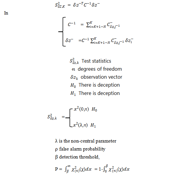
The higher the accuracy of the IMU, the more accurate its measurement data, and the higher the accuracy of the deception detection algorithm. The accuracy of the IMU determines the response speed of the deception detection algorithm. For a Kalman filter, the measured innovation vector is shown in equation (4), which is the difference between the actual observation vector and the one-step prediction vector , that is

The innovation vector can indicate whether the measurement is consistent with the estimate, and its size is determined by the measurement error and the accuracy of the system model. When the accuracy of the system model is high, the Kalman filter information can represent the actual measurement error. The covariance of the innovation is the sum of the values converted into the measurement space by the measurement noise covariance and the error covariance of the state estimate, that is
 Smaller, slowly building up deviations between measurements and state estimates can be identified by a statistical test consisting of the latest N measurements. N is the "detection window". When N is 1, it is snapshot deception detection, and when N is greater than 1, it is continuous deception detection. Chi-square test is often used in the innovation deception detection algorithm, and the innovation test statistic is constructed as
2.2 The impact of INS error propagation on observation information
IMU accuracy is usually characterized by bias and random noise. The bias error term exists in all accelerometers and gyroscopes. In most cases, the bias error term is the main component of all errors in inertial instruments; in addition, it is affected by a variety of Effect of Error Sources,All inertial sensors exhibit random noise.
In the GNSS/INS combined system, since the output results of GNSS and INS must be fused and filtered every interval, when considering the impact of IMU accuracy on new information, the error propagation model of INS can be equivalent to a short-time uniform straight line Error propagation. The speed error is the integral of the acceleration error. The speed and position errors caused by the constant acceleration deviation are

The measured specific force can be approximated as the opposite value of acceleration when moving at a uniform speed on a horizontal plane for a short period of time. Then the position and velocity errors caused by the gyro bias can be simply expressed as

In the formula, is the acceleration due to gravity. In addition, in a well-designed system, the inertial sensor noise will be the largest noise source, which can be obtained from the inertial navigation error variance or the time update covariance matrix of the Kalman filter. In order to quantify the relationship between inertial navigation error and time, if the one-sided power spectral density of accelerometer noise is , then the standard deviation of the velocity error and position error caused by the noise is

In the same way, the standard deviation of the speed error and position error caused by noise is

The IMU accuracy reference for different performance levels is shown in Table 1.

Table 1 IMU accuracy reference for different performance levels
According to the IMU performance parameters shown in Table 1, calculate the pseudorange prediction error caused by INS error propagation at different state propagation intervals. Because the satellite velocity position at k can be obtained from the GNSS satellite ephemeris, assuming that the receiver position is accurately known, then The projection of the position error caused by the INS in the line of sight direction of the receiver and satellite is the pseudorange prediction value error. Consider the situation with the largest error, that is, we have

The calculation of propagation errors under different levels of IMU and different error propagation times is shown in Table 2.

Table 2 Pseudorange error
Therefore, the observation value error caused by the IMU accuracy not only increases as the IMU accuracy decreases, but also increases as the error propagation time increases. Since each iteration of the closed-loop Kalman filter corrects the system itself, the INS error propagation time in integrated navigation is the state propagation interval of the Kalman filter, that is, the observation value error caused by the IMU accuracy increases as the Kalman filter state propagation interval increases. And increase.
When using integrated navigation information to detect spoofing interference, it is usually assumed that the output of the INS within the state propagation interval is relatively accurate; however, due to the influence of IMU accuracy, the pseudorange error caused by the INS is close to or even exceeds that caused by spoofing interference at the same time. When the pseudorange deviates, the results obtained by innovation detection will become unreliable. It can be seen from the analysis in Section 1.1 that when there is an INS propagation error at time , the observation vector is also an observation innovation vector in the closed-loop correction, and the pseudorange observation part can be expressed as

The principle of innovation deception detection is to take advantage of the fact that innovation obeys a zero-mean Gaussian distribution when there is no deception interference, and obeys a Gaussian distribution with a non-zero mean when there is deception interference. However, if the pseudorange deviation caused by IMU accuracy is large, it will destroy the characteristics of the zero-mean distribution of innovations, thereby affecting the deception detection algorithm.
It can be seen that when using innovation for deception detection, there are requirements for IMU performance, that is, the total deviation of the observation value caused by the IMU within the detection window cannot exceed the detection threshold of the innovation deception detection algorithm.
3 Experiment and result analysis
3.1 Experimental design
In order to compare the impact of different IMU accuracy on deception detection algorithms, it is considered that the observation value error caused by IMU accuracy not only increases with the decrease of IMU accuracy, but also increases with the increase of Kalman filter state propagation interval and detection window length. Large, experiments are mainly designed from the following aspects:
(Experiment 1) Apply the same ramp-type deception, and analyze and compare the impact of different precision INS on the deception detection algorithm within the same state propagation interval.

Figure 2 Detection situation at different IMU accuracy
(Experiment 2) Apply the same ramp-type spoofing to analyze and compare the impact of lower-precision INS propagation intervals in different states on the spoofing detection algorithm.

Figure 3 Detection situation at different state propagation intervals
(Experiment 3) Apply the same ramp-type spoofing, and analyze and compare the effects of spoofing detection algorithms with different detection windows on low-precision INS and the same state propagation interval.

Figure 4 Detection conditions in different windows
Combining the results of the three experiments, it can be seen that IMU accuracy will indeed affect the detection effect of the deception detection algorithm. When using consumer-grade IMUs, the impact will be greater, and it may even cause the deception detection algorithm to fail. Specifically, when there is no interference from spoofing, the spoofing detection statistics are still affected by the error caused by the IMU accuracy, causing the spoofing detection statistics to exceed the threshold. And experiments show that the impact of low-precision IMU can be reduced by adjusting the Kalman filter state propagation interval and the detection window of the spoofing detection algorithm.
Summarize
Through theoretical derivation and simulation experiments, this paper comparatively analyzes the impact of different IMU accuracy on the tight combination anti-spoofing algorithm, and experimentally analyzes the effects of two factors: the Kalman filter state propagation interval and the detection window of the spoofing detection algorithm. The results show that the influence of different IMU accuracies on pseudorange estimates causes the innovation detection amount to no longer be zero mean when there is no spoofing interference. The use of innovation-based spoofing detection algorithms has requirements for IMU accuracy. With the detection probability and Kalman As the filtering state propagation interval increases, the requirements for IMU accuracy increase.
Specifically:
1) IMU accuracy does affect the detection effect of the deception detection algorithm, and consumer-grade IMUs can cause false alarms in the chi-square deception detection algorithm.
2) Under the condition that the state propagation interval of the Kalman filter is less than or equal to 0.1 s and the detection window used is equal to 1, the false alarm problem of the chi-square deception detection algorithm caused by the consumer-level IMU is solved, but when there is a detection greater than 50 s extension.
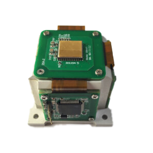
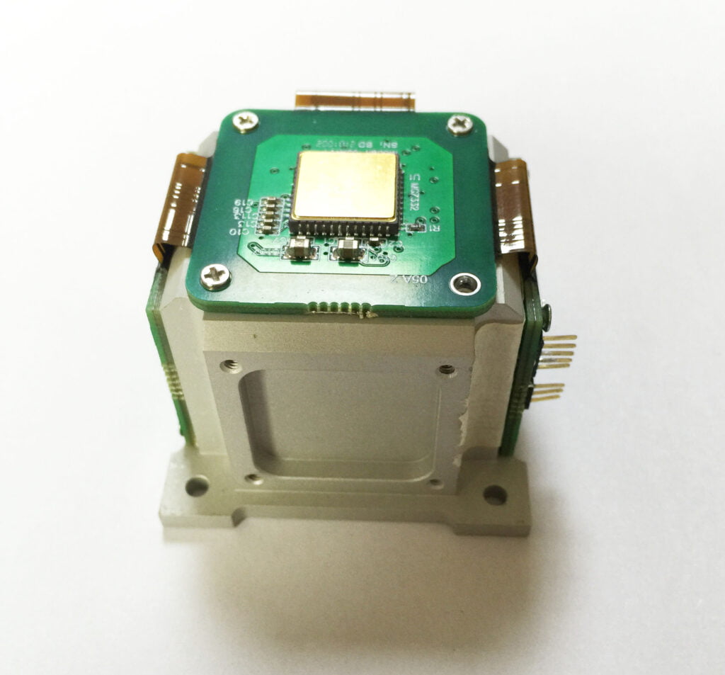
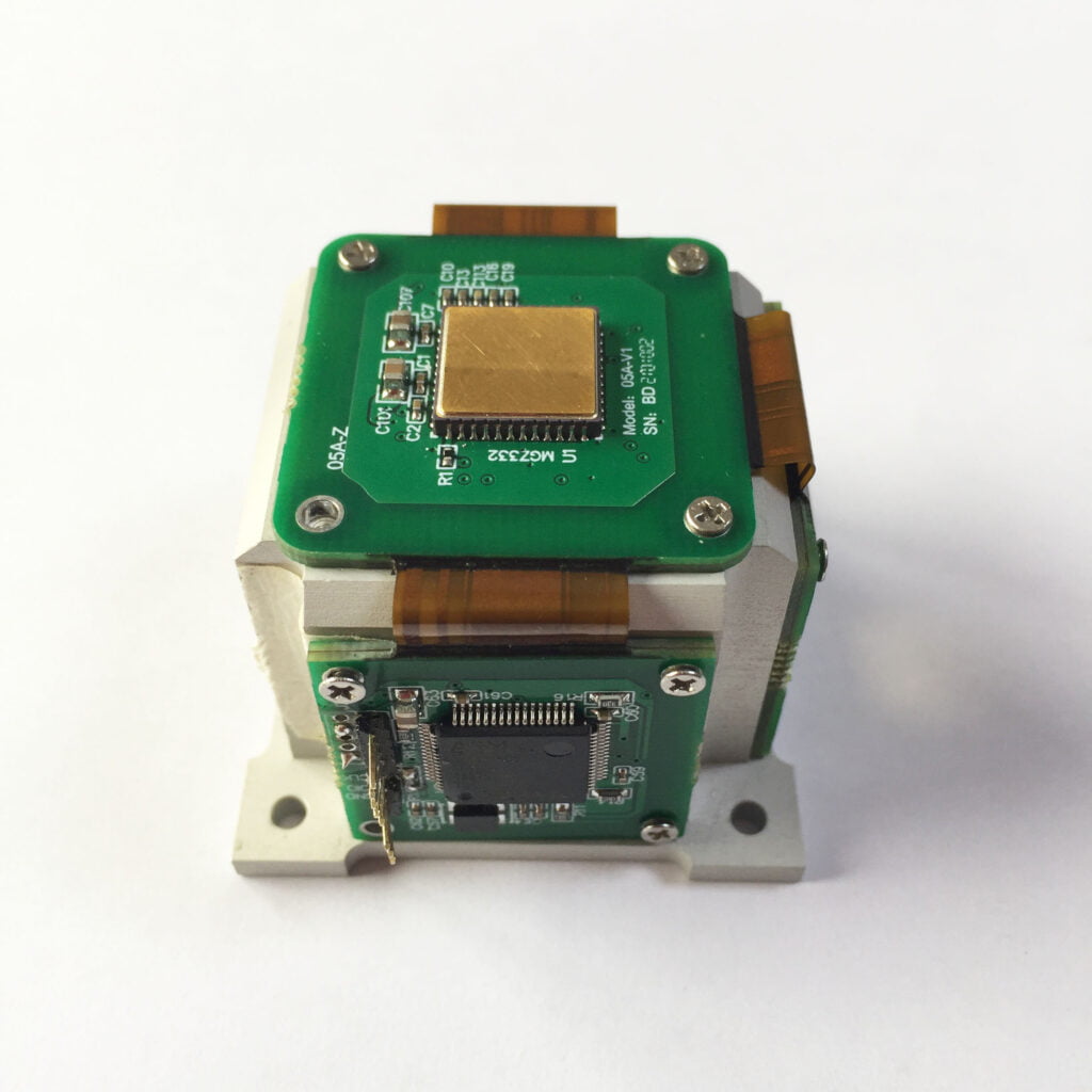
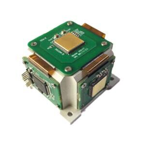
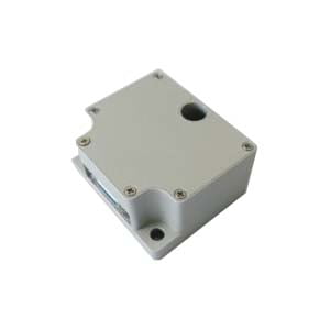
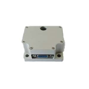
Then the domestic company ERICCO independently develops IMU, which is divided into navigation level and tactical level. Navigation-level ER-MIMU01 and ER-MIMU05 can independently seek north. Other IMUs only need to add GNSS and magnetometers to the IMU to independently seek north. They also have a wide range of applications. For example, ER-MIMU03 and ER-MIMU07 can be used in drones. This product has a built-in acceleration sensor and gyroscope, which can measure linear acceleration and rotational angular velocity in three directions, and obtain the carrier's velocity through analysis. Attitude, velocity and displacement information enable precise positioning.
If you want to learn about or purchase IMU products, please contact our relevant personnel.
More Technical Questions
1.IMU algorithm: data acquisition & calculation of speed and direction
2.IMU working principle & Tactical grade IMU product recommendations
3.Choosing an IMU: FOG IMUs vs MEMS IMUs
4.Application of IMU in the Field of Drones
6.What is the Difference Between IMU and AHRS?
Products in Article