IMU(inertial measurement unit) is a sensor capable of measuring and outputting three axial accelerations and angular velocities. By combining a MEMS inertial device with an IMU, the error of the MEMS device can be modulated. This technology is mainly based on the principle of rotational modulation, changing the output signal of the MEMS device by rotating the IMU, thereby achieving error compensation and modulation. With the rapid development of microelectromechanical systems (MEMS) technology, MEMS inertial devices have been widely used in many fields. However, the error sources and effects of MEMS inertial devices are still a problem that needs attention and resolution. Among them, low signal-to-noise ratio and drift are the main factors affecting its application range. Therefore, it is of great significance to carry out research on error modulation technology of MEMS devices based on IMU rotation. The following is mainly introduced in three parts. They are: wavelet noise reduction, low signal-to-noise ratio and drift, and MEMS device error modulation technology based on IMU rotation.
1.MEMS wavelet noise reduction
Wavelet analysis is a rapidly developing new field in current applied mathematics and engineering disciplines. After years of exploration and research, an important mathematical formal system has been established, and the theoretical foundation has become more solid. Compared with Fourier transform, wavelet transform is a local transformation of space (time) and frequency, so it can effectively extract information from signals. Multi-scale detailed analysis of functions or signals can be performed through operation functions such as scaling and translation, which solves many difficult problems that cannot be solved by Fourier transform.
Noise reduction is one of the main uses of wavelet analysis in the field of signal processing. Denoising a signal actually suppresses the noise in the signal.
Use part to enhance the useful part of the signal process. The denoising process of the inertial device output signal is as follows: 3 steps:
Step 1: Wavelet decomposition of the signal. Refer to Figure 1. Select an appropriate wavelet and determine the level of decomposition, and then perform decomposition calculations.

Figure 1 Wavelet decomposition of signal
Step 2: Threshold quantization of high-frequency coefficients of wavelet decomposition. Select a threshold value for the high-frequency coefficients at each decomposition scale to perform soft threshold quantization processing.
Step 3: Wavelet reconstruction. One-dimensional wavelet reconstruction is performed based on the low-frequency coefficients of the lowest layer of wavelet decomposition and the high-frequency coefficients of each layer of decomposition.
Among these three steps, the most critical is how to select the threshold and perform threshold quantification processing. To some extent, it is related to the quality of signal denoising.
The wavelet basis function is determined based on the characteristics of the signal to be processed. The ideal wavelet basis should have the following properties:
1) Linear phase characteristics, which can reduce or eliminate the distortion of the reconstructed signal at the edges;
2) Compact support characteristics. The shorter the support, the lower the computational complexity of the wavelet transform, making it easier to implement quickly;
3) The evanescent moment characteristic determines the degree to which energy is concentrated in low-frequency components after wavelet transformation.
The Daubechies wavelet selected in this paper is a compactly supported orthogonal wavelet that has an extreme phase and the highest vanishing moment for a given support width. A related scale filter is the minimum phase filter. Theoretically, as the scale increases, the filtering effect will be better, but at the same time the amount of calculation will increase, and the calculation rounding error will also increase. Therefore, in practical applications, the accuracy requirements and calculation amount should be considered comprehensively. Determine the transform scale of the required wavelet. In addition, even if the carrier is in a static base environment, due to the influence of various external factors, certain external dynamic interference will be introduced into the output of the gyroscope and accelerometer, and the dynamic interference from the base will be introduced into the test output of the gyroscope. . Relative to the useful signal, these disturbances are high-frequency random interference. Therefore, wavelet transform can be used for filtering, which will effectively reduce the interference of disturbance and device noise.
2.Low signal-to-noise ratio and drift
Low signal-to-noise ratio and drift are the main factors affecting the errors of MEMS inertial devices, which are mainly reflected in the following aspects:
2.1 Signal interference and noise: MEMS inertial devices will be interfered by various external factors during operation, such as electromagnetic noise, thermal noise, etc. These interferences will cause the signal-to-noise ratio of the signal to be reduced. Low signal-to-noise ratio will affect the measurement accuracy and stability of MEMS inertial devices.
2.2 Stability of the output signal: Drift refers to the stability problem of the output signal of the MEMS inertial device. Due to the physical characteristics of MEMS devices, their output signals may change with time, temperature and other factors, resulting in measurement errors.
2.3 Analysis of error sources: Low signal-to-noise ratio and drift are mainly caused by problems in the design, manufacturing and packaging of MEMS inertial devices. For example, defects introduced during the manufacturing process, stress during packaging, temperature changes, etc. may cause changes in the output signal of the MEMS inertial device.
2.4 Algorithm and data processing: In practical applications, algorithms and data processing technology are needed to reduce the impact of low signal-to-noise ratio and drift on MEMS inertial devices. For example, filters, compensation algorithms, etc. can be used to improve the measurement accuracy and stability of MEMS inertial devices.
2.5. Testing and verification: In order to evaluate the impact of low signal-to-noise ratio and drift on MEMS inertial devices, sufficient testing and verification are required. By building an experimental platform and conducting comparative experiments, the performance of MEMS inertial devices can be objectively evaluated.
In summary, low signal-to-noise ratio and drift are the main factors affecting the errors of MEMS inertial devices. They need to be reduced by in-depth analysis of their causes, the use of effective algorithms and data processing technology, and sufficient testing and verification. Impact on MEMS inertial devices.
3.MEMS device error modulation technology based on IMU rotation
In the MEMS device error modulation technology based on IMU rotation, the MEMS output information first needs to be preprocessed. Since there are random noise signals in the output signals of MEMS devices, these noise signals will adversely affect the measurement accuracy and stability of MEMS devices. Therefore, effective noise reduction technology needs to be used to process MEMS output information. Wavelet noise reduction technology is an effective signal processing method, which can effectively eliminate random noise signals and improve the device output signal-to-noise ratio. By applying wavelet noise reduction technology to MEMS output information, effective modulation of MEMS device errors can be achieved.
During the error modulation process, it is necessary to analyze the error modulation principle under the IMU rotation scheme. The rotation of the IMU can change the output signal of the MEMS device. Through a reasonable rotation scheme, effective compensation and modulation of the MEMS device error can be achieved. To achieve this goal, the rotational modulation scheme needs to be optimized and designed. The optimization goal can be to improve the measurement accuracy, stability, reliability, etc. of MEMS devices.
Furthermore, the engineering feasibility of rotational modulation needs to be explored. In practical applications, the rotation modulation scheme needs to take into account the actual application environment and conditions, such as rotation angle, rotation speed, rotation method, etc. These factors will all have an impact on the implementation of rotational modulation. Therefore, these factors need to be comprehensively considered and optimized to ensure the feasibility and effectiveness of rotational modulation.
In order to verify the effectiveness of the MEMS device error modulation technology based on IMU rotation, a MEMS rotation experimental environment can be built and experimental research can be carried out. MEMS devices of different types and specifications can be tested and analyzed in the experiment to evaluate the applicability and effect of the technology. At the same time, it can also be compared and analyzed with other error compensation technologies to further verify the advantages and potential of this technology.
Summarize
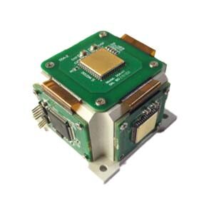
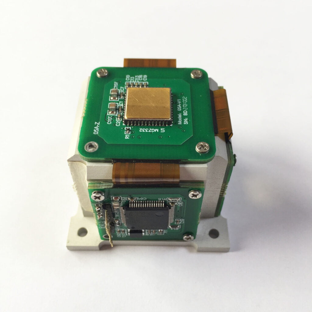
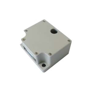
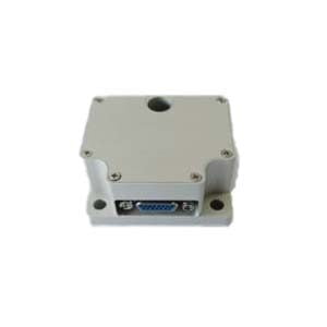
In short, the research on MEMS device error modulation technology based on IMU rotation is of great significance and application value. Through the research and application of this technology, the measurement accuracy, stability and reliability of MEMS inertial devices can be effectively improved, and the application and development of MEMS technology in various fields can be further promoted. The low signal-to-noise ratio and large drift of existing MEMS inertial devices have become technical bottlenecks that make it difficult to achieve rapid improvement in a short period of time. This paper uses the idea of averaging technology in signal processing to propose a MEMS device error modulation method based on IMU rotation and implements wavelet analysis to complete inertial device noise reduction processing under the IMU rotation state. ERICCO is a company specializing in the research and development of inertial navigation products. The independently developed MEMS IMU is trusted by consumers across the country. MEMS IMU can achieve light weight, small size, high performance, and can greatly save installation space, reduce carrier load, and reduce user expenses. For example, the navigation-level ER-MIMU-01 can independently seek north. The gyroscope included in the product has relatively high accuracy. Compared with other inertial navigation companies, it is relatively friendly to consumers.
If you want to know more about IMU, please contact our relevant technical personnel.
More Technical Questions
1.IMU self-calibration based on factorization
2.Choosing an IMU: FOG IMUs vs MEMS IMUs
3.Influence analysis of IMU accuracy on spoofing detection algorithm
4.IMU working principle & Tactical grade IMU product recommendations
5.IMU algorithm: data acquisition & calculation of speed and direction
6.Inertial Measurement Unit Error Calibration
Products in Article