MEMS-IMU has many advantages over traditional IMUs, such as small size, low cost, low power consumption and high integration. MEMS IMU is widely used in the military field, such as tactical guided weapons. In recent years, the application scope of MEMS-IMU in the civilian field has been continuously expanded, such as drones, underwater equipment, car navigation, etc. At present, the performance indicators of MEMS inertial sensors at home and abroad cannot meet the requirements of inertial navigation. The performance indicators of the most advanced MEMS gyroscopes can only reach the tactical level, and they are easily interfered in the actual working environment, reducing the output accuracy. MEMS accelerometer performance is also inferior to traditional quartz accelerometers. This chapter will comprehensively analyze various errors and compensation solutions of MEMS-IMU.
The following table shows the main indicators for judging gyroscope performance. Different grades have different accuracy levels.

The errors of MEMS-IMU mainly include errors of MEMS sensors and MEMS-IMU integration errors. The errors of MEMS IMU will be analyzed in detail from these two aspects below.
 1.MEMS inertial sensor error analysis
1.1 Zero offset
The bias errors of MEMS accelerometers and MEMS gyroscopes mainly include bias, bias stability and bias repeatability. Zero-bias repeatability and zero-bias can be eliminated through initial alignment. Zero-bias stability refers to the degree of drift of its output angular velocity or acceleration over time under a certain input. This is related to the structure, design and external environment of the MEMS sensor.
1.2 Scale factor error
Since MEMS gyroscopes and MEMS accelerometers convert signals between signals through a scale factor, the error in the scale factor will directly affect the output error of the MEMS accelerometer and MEMS gyroscope. The error of the scale factor is divided into temperature drift and nonlinear error. It is difficult to measure the relationship between the scale factor and temperature through experimental testing for MEMS accelerometers, because centrifuges generally do not have temperature control devices, while MEMS gyroscopes can be temperature controlled. The relationship between the scale factor and temperature was measured using the turntable.
1.3 Non-sensitive axis coupling error
The non-sensitive axis coupling error refers to the error output caused by the non-orthogonality of the sensor structure itself when there is input on the non-sensitive axis. The non-sensitive axis mutual coupling error can be expressed by Equation

Formula1:Insensitive axis mutual coupling error1-1
Among them, VX, VY, and VZ represent the output voltages of the x, y, and z-axis sensors, Input is the external input, and K is the mutual coupling error coefficient. It can be seen that the expression of the coupling error of the MEMS accelerometer and the MEMS gyro is the same as the installation error expression of the IMU can be processed together.
1.4 Acceleration sensitivity
The acceleration sensitivity of the MEMS gyroscope refers to the output of the MEMS gyroscope's sensitive acceleration, which is an error term with a large impact. Because most MEMS gyroscopes are based on mechanical vibration, they may be affected by acceleration, especially in working environments with large accelerations. For example, when the acceleration of the carrier is 20g and the duration is 10s, when the acceleration sensitivity is 0.05 (° /s)/g, the angle error produced by this is approximately 10°. Such a large angle error has a great impact on the MEMS-IMU attitude solution, so acceleration sensitivity is an error term that cannot be ignored.
1.5 Random noise
The random noise of the structure and the random noise of the circuit are the main components of the random noise of the MEMS inertial sensor. The random noise of the structure is mainly mechanical thermal noise. The random noise of the circuit includes the thermal noise of the circuit, 1/f noise, shot noise and g-r. Noise, etc., the biggest impact on the performance of MEMS sensors is mechanical thermal noise and circuit thermal noise, which are the main research objects.
Brown's force is the source of mechanical thermal noise. Its principle is that gas molecules or liquid molecules produce random collisions with mechanical particles. This effect directly affects the sensitivity and resolution of the MEMS sensor and increases the random noise during measurement. Because the structure of the MEMS sensor is on the micron or even nanoscale, the impact of molecular motion cannot be ignored.
For capacitive MEMS inertial sensors, the equivalent Brown noise acceleration is

Formula2:Equivalent Brown noise acceleration1-2

Formula3: 1-3

Circuit thermal noise refers to the irregular thermal movement of carriers in a conductor when the temperature is above zero. Due to this irregular thermal movement, the current in the circuit deviates from the average fluctuation, resulting in voltage fluctuations. The power spectrum distribution of this thermal noise is
 Formula4: The power spectrum of thermal noise1-4
Among them, R is the resistance of the conductor. From the above formula, we can know that the power spectrum of random noise is constant in the entire frequency band. However, the noise can be suppressed through low-pass filtering to prevent it from spreading in the form of integrals in navigation and positioning.
2.MEMS-IMU integrated error analysis
Sensor mounting non-orthogonality errors and lever-arm effect errors are the main components of MEMS-IMU integration errors.
2.1 Sensor installation error
The sensor installation error of MEMS-IMU is mainly due to the non-orthogonality of the MEMS-IMU shell, the sensor installation error and the non-orthogonality of the sensor itself. As shown below.
 where xByBzB is the reference orthogonal coordinate system, xyz is the coordinate system of the gyroscope group or accelerometer group, θij (i, j=x, y, z) represents the installation error angle, where i represents the measurement axis, j represents the measurement axis around j The installation error angle caused by shaft rotation is positive in counterclockwise direction. The transformation from the reference coordinate system to the axis coordinate system is as follows.
The form is consistent with the formula (1-1) and does not need to be distinguished. The installation error of the MEMS gyroscope can be evaluated using the turntable test method. Given different rotational speeds, the installation error angle parameters can be obtained by measuring the output at different rotational speeds. The static tumbling test method can be used to evaluate the installation error of the MEMS accelerometer, and the installation error angle parameters of the MEMS accelerometer can be solved by measuring the output at multiple positions.
2.2 Lever arm effect error
Since the sensor of the combined MEMS-IMU is installed separately, when the carrier rotates around a certain rotation axis, the sensor will be subject to additional centrifugal acceleration and tangential acceleration, resulting in output errors of the MEMS accelerometer and MEMS gyroscope. The error is related to the rotation angular rate. Directly proportional.
3 Calibration
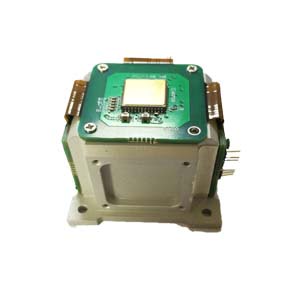
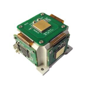
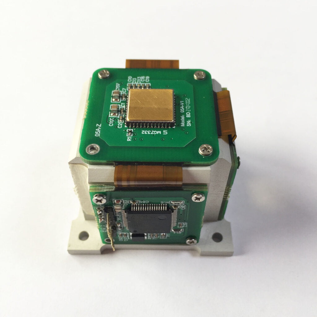
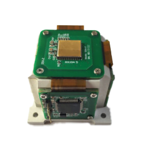
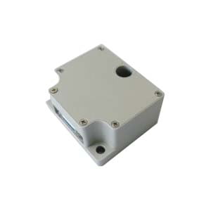
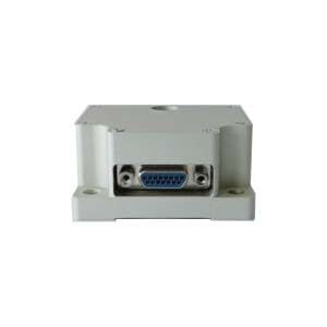
According to the above calibration method, the single-axis turntable can be used to complete the angular rate calibration experiment and position calibration of the MEMS gyroscope and MEMS accelerometer, and solve the various error coefficients in the error model. The experimental platform is shown in the figure, and the performance indicators of the experimental platform as follows.


4 Calibration method verification
Use the obtained error coefficients to compensate the MEMS gyroscope and MEMS accelerometer, then install the MEMS-IMU on the turntable with the Z-axis facing upward and fix it, and control the temperature of the turntable to rise from -40° to 80°, and then from 80° ° drops to -40°, collect the output data of MEMS-IMU respectively and save them. Use MATLAB to draw the saved data into a graph, and the results are shown in the figure below.


Comparison of data before and after MEMS IMU compensation
As can be seen from the data before and after X-axis compensation in the figure above, the maximum output error of the gyro before compensation reached 0.025°/s, and after compensation it was reduced to 0.02°/s, and it can also be seen from the figure that the error is increasing. The data at 0.01°/s-0.025°/s is significantly reduced, and the errors in the Y and Z axes are also reduced. This shows that the calibration method in this article is feasible.
Summarize
Analyze various error sources of MEMS-IMU, including device errors and integration errors. Based on the main error sources of MEMS gyroscopes and MEMS accelerometers, corresponding error models were established, a calibration experimental plan was designed, and the calibration experimental plan was experimentally verified, confirming that the given calibration method is feasible and can improve MEMS-IMU measurement accuracy. Regarding the accuracy of MEMS IMU, I have to say that the MEMS IMU independently developed by ERICCO has high accuracy, small size, light weight and low power consumption. For example, the gyroscopes and accelerometers in ER-MIMU01 and ER-MIMU-02 are also more accurate. Strict measures have also been taken for the error calibration of the IMU.
If you want to learn about or purchase an IMU, please contact our relevant personnel.
More Technical Questions
1.IMU self-calibration based on factorization
2.Influence analysis of IMU accuracy on spoofing detection algorithm
3.IMU algorithm: data acquisition & calculation of speed and direction
4.Inertial Measurement Unit Error Calibration
5.IMU working principle & Tactical grade IMU product recommendations
6.Choosing an IMU: FOG IMUs vs MEMS IMUs
Products in Article