MEMS gyroscope is small in size, light in weight, has the advantages of intelligence, multi-function and high integration, but it is easy to be affected by its own or environmental factors, in order to ensure its accuracy to meet the measurement requirements, it is necessary to compensate the error of MEMS gyroscope. There are many sources of error in the inertial system, the production and assembly of the instrument itself, the various movements of the carrier (including line motion and angular motion), as well as external factors such as temperature, gravity field, shock vibration, etc., will cause various errors in the inertial device, and MEMS gyroscope has more errors than traditional components. The determination of the error term and the compensation of various errors become a very important step.
Allan variance method is often used to analyze the random error of gyroscopes. The random drift rate of gyroscope is the error term caused by some uncertain factors of gyroscope, which not only includes the error caused by the factors not considered in the error model, but also includes the error caused by the instability of the error coefficient. It is a comprehensive error term of gyroscope, and it is also the main performance index to measure the performance of gyroscope.
In IEEE standard, the random error of gyroscope is usually analyzed by PSD and Allan variance method. Allan variance method was proposed by David Allan of the National Bureau of Standards of the United States in 1966, initially used to study the stability of high-precision oscillators, the method has gradually been used to identify the random error of inertial sensors, it is a time-domain based analysis method, can be used to analyze the error characteristics of any precision measuring instrument, accurately identify the type of noise. The main feature of Allan variance method is that it is very easy to characterize and identify various error sources and the statistical characteristics of the whole noise, and precisely determine the characteristic parameters of noise, which is easy to calculate and easy to separate. It provides a way to identify and quantify the different noise terms present in the measurement data.
The output angular velocity rate of the gyroscope is sampled at a time interval t during the sampling process. N points are collected in the whole process, and the continuous sampling time is T. All the obtained data are divided into K groups, each group contains M data, so that the sampling time of each group is tM=t*M, tM is called correlation time, and the average value of each group of data is:
![]()
wi is the i th point in the K th subset.
The variance between each different subset is called the Allan variance and is defined as:
![]()
σ2 (tM) represents the Allan variance when the correlation time is tM.
MEMS gyroscope random noise is generally divided into five independent parts, namely quantization noise, angle random walk, bias instability, rate random walk and rate ramp. Taking the correlation time tM as the independent variable, the graph corresponding to the Allan variance is the Allan variance graph. In practice, the Allan standard deviation curve is used to describe, and then the Allan standard deviation curve can be logarithmically transformed to get the commonly used Allan hyperbola. Different random errors of MEMS gyroscope correspond to different slopes on the Allan hyperbolic plot (Table 1).
| Allan variance | noise factor | slope |
| σ2Q = 3Q2/τ2 | quantizes the noise factor Q/ s-1 | -1 |
| σ2N = N2 /τ | angle random walk coefficient N/(°·h-1/2) | -1/2 |
| σ2B =(0.6648B)2 | bias instability B/(°·h-1) | 0 |
| σ2K= (K2/3)τ | angular rate random walk coefficient K/(°·h-3/2) | 1/2 |
| σ2R= (R2/2)τ2 | rate ramp coefficient R/(°·h-2) | 1 |
Table 1 Correspondence between Allan variance and random noise coefficient of MEMS gyroscope
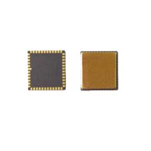
The ADIS 16365 inertial device was used as the data source, which was placed at rest, the sampling frequency was set to 100Hz, and after 20min preheating, the output of the three-axis gyroscope was collected for 4h, and the Allan variance analysis was performed on the output data, as shown in Figure 2.
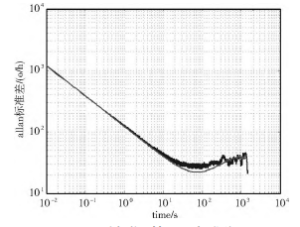
Figure 1 Gyroscope x-axis Allan standard deviation
| Angle random walk | bias instability | Rate random walk | rate ramp | quantization noise |
| 5.4005 | 2.1869 | 5.6429 | 109.5779 | 83.3189 |
Table 2 Identification results of each random error item of gyro
Combined with Table 1, the identification results of each random error item of the gyroscope are obtained, as shown in Table 2. Quantization noise refers to the distortion caused by the quantization of amplitude and time after signal decoding in coded communication. A large quantization noise figure indicates that the acquisition accuracy of the system is low. The angle random walk reflects the white noise characteristic in the angular rate signal of gyroscope inertial device, which is represented as an angle random walk after integration. Bias instability is the sensor itself caused by random fluctuations, it is when the angular velocity is zero, the measurement of the gyroscope output with its mean dispersion degree. Bias instability is the value of the lowest point of the Allan curve, which represents the best stability that the gyroscope can achieve after compensation by the complete error model. If a horizontal line passes through this lowest point, the value of its intersection with the vertical axis is divided by 0.6648 to obtain the maximum value of bias instability.
In inertial system, the precision of gyroscope determines the accuracy of the whole system to a large extent, and the research of gyroscope error is the core work of the inertial system. According to the error sources of MEMS devices, the Allan variance method is introduced in this paper.
We also generally use bias stability 10-second smoothing to reflect the performance of MEMS gyroscope, and the Allan variance is generally three times that of 10-second smoothing. For example, the tactical MEMS gyroscope ER-MG-056 has a bias stability of 5dph smooth in 10 seconds. ER-MG-067 has a high bias stability of 3deg/hr in 10 seconds.
If you are interested in MEMS gyro, please contact us.
More Technical Questions
1.Integrated method of three-axis MEMS gyroscope
2.Bandwidth test method of MEMS gyroscope
3.Impact resistance technology of MEMS gyroscope
4.Research on driving mode of MEMS gyroscope
5.Analysis of drive loop noise of MEMS gyroscope
6.Comparative analysis of integrated modes of three-axis MEMS gyroscope
Products in Article