Because there is no need to integrate rotating parts inside the MEMS gyroscope, but through an entire micro mechanical component made of silicon to detect the angular velocity, MEMS inertial sensors are very easy to miniaturize and mass produce, and have the advantages of wide dynamic range, high measurement accuracy, and good environmental adaptability.
Bandwidth is one of the important indexes of MEMS gyroscope. The commonly used bandwidth test method of MEMS gyroscope is the angle vibration method, which makes the MEMS gyroscope perform angular vibration at different frequencies through the Angle vibration table, synchronously records the MEMS sensor output signal and the Angle vibration table motion signal (MEMS gyros input signal), and then calculate the frequency characteristics according to the MEMS gyro input and output signals.
In this paper, the bandwidth measurement method of MEMS sensor is discussed. In the following, the traditional gyro bandwidth measurement method and improved bandwidth measurement method are discussed.
Traditional gyro bandwidth measurement method
Fix the test shaft vertically down on the Angle shaker. Oscilloscope is used to record the waveform of the test shaft output and the reference signal of the simulation turntable. After starting the micro mechanical gyroscope to work normally, start the simulation turntable, and swing according to different vibration frequencies and amplitudes. Observe the peake-to-peak time interval T of the MEMS gyroscope rate signal output and the reference signal of the simulation turntable, and T should meet the time correspondence of [0°,90°].
The comparison diagram of signal waveforms is shown in Figure 1, the installation diagram is shown in Figure 2, and the test waveform diagram is shown in Figure 3.
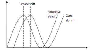
Figure 1 Bandwidth test signal waveform comparison diagram
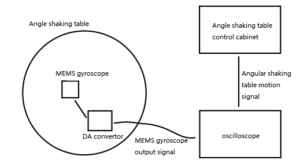
Figure 2 Bandwidth test installation diagram
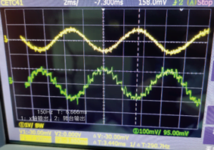
Figure 3 Bandwidth test oscilloscope sampling effect diagram
In the traditional bandwidth test method, the motion signal of the Angle shaker is generated by the control cabinet of the turntable, which is usually an analog signal. The output signal of the micromechanical gyroscope needs to be converted by DA and then tested and calculated by oscilloscope.
Traditional bandwidth testing methods have the following shortcomings:
1) The number of products tested each time is limited by the oscilloscope channel, generally a maximum of 3 products are measured at the same time;
2) There are errors in measuring time width with oscilloscope;
3) The delay of DA conversion waveform and Angle shaker motion signal at different frequencies, and the amplitude of Angle shaker motion signal at different frequencies will have different degrees of attenuation;
4) When the digital output frame rate of the detected product is low, the DA conversion waveform is easy to distort.
Improved gyro bandwidth measurement method
In practice, due to the large number of MEMS inertial sensors delivered, traditional bandwidth measurement methods are not suitable for batch detection.
Based on the angular vibration method, the improved gyro bandwidth measurement method no longer takes the angular vibration table motion signal as the reference signal, but uses the gyroscope output signal with known bandwidth as the reference signal, so that the attenuation and delay of the angular vibration table signal can be no longer considered.
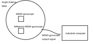
Figure 4 Improved bandwidth test installation diagram
In Figure 4, the relative phase shift and relative amplitude change can be calculated by taking the vibration response curves of multiple gyroscopes at different frequency angles at the same time, simply by knowing the bandwidth of the reference MEMS gyroscope.
1. Specific test plan
The test axes of the reference MEMS gyroscope and several tested gyroscopes are fixed vertically down on the Angle vibration table. The industrial computer is used to collect the real-time data of the gyroscope. After starting the micro mechanical gyroscope to work normally, start the simulation turntable, swing according to different vibration frequencies and amplitudes, record all the data, and then draw the angular vibration response curve in the same coordinate system through playback to calculate the relative phase shift and amplitude attenuation of peak-to-peak value points between each curve.
The comparison diagram of signal waveforms is shown in Figure 1, and the actual installation diagram is shown in Figure 5.
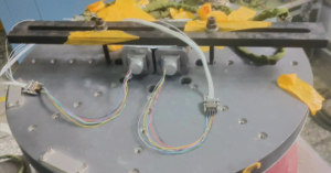
Figure 5 Improved bandwidth test actual installation diagram
2. Test the effect
The test waveform diagram is shown in Figure 6 and Figure 7.
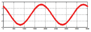
Figure 6 Vibration response curve of improved bandwidth test at 1Hz
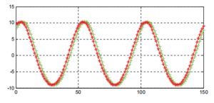
Figure 7 Vibration response curve of improved bandwidth test at 40Hz
It can be clearly seen from Figure 7 that the response bandwidth of the two gyroscopes is different. The bandwidth of the tested gyroscope is lower than that of the reference gyroscope, and the relative phase shift difference is about 15°.
In actual mass production, the benchmark gyroscope is set as the threshold, and the improved bandwidth test method can be used to quickly measure the gyroscope products that meet the bandwidth design and those that do not meet the bandwidth design.
Conclusion
This paper introduces the traditional bandwidth test and the improved bandwidth test for MEMS gyroscope. The improved bandwidth test method is more suitable for the bandwidth test of batch products. By testing the real product with an example, the relative bandwidth shift of the test result is 15°, which can effectively evaluate the relative bandwidth of the tested product.
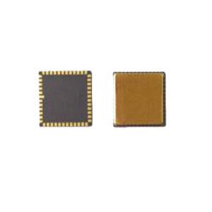
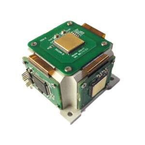
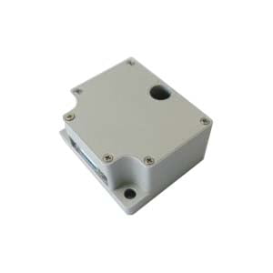
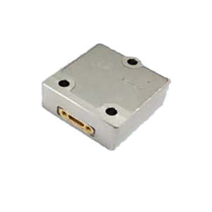
Ericco, as an experienced MEMS sensor R & D and manufacturer, has carried out strict bandwidth testing on MEMS sensor. For example, the two MEMS inertial sensors in the navigation class have a bandwidth of 12Hz for the ER-MG2-50/100 for ground navigation and a bandwidth of 50-100Hz for the ER-MG2-300/400 for air and sea navigation. At the same time, Ericco also focuses on two - and three-axis MEMS gyroscopes, two - axis MEMS inertial sensors are mainly used for attitude measurement, and three - axis MEMS gyroscopes can be used for system development. Bandwidth is only one of the important indicators of MEMS sensor, want to know more important indicators, please contact us.
If you want to learn more about MEMS sensors, please click on the related articles and products below.
More Technical Questions
1.Impact resistance technology of MEMS gyroscope
2.Research on driving mode of MEMS gyroscope
3.Packaging of MEMS gyroscope: Structural Analysis of Deep Hole Packaging
4.Bias Temperature Compensation Analysis of MEMS Gyroscope
5.System error and calibration of MEMS gyroscope
6.The analysis of damping in MEMS gyroscope
Products in Article