

In recent years, microelectronics technology and micro-manufacturing technology have developed rapidly, promoting the emergence of MEMS gyroscope systems. MEMS gyroscopes are manufactured based on MEMS technology. Micromechanical systems are based on integrated circuit technology and micromachining technology to integrate microstructures, microsensors and control circuits on a very small chip. Its special manufacturing technology and processing technology give MEMS systems many advantages, such as small size, easy integration, low cost, and light weight. MEMS gyroscopes are widely used due to their advantages that traditional gyroscopes cannot match. This article will analyse the errors of MEMS gyroscopes. The following will introduce the working principle, error analysis and error identification indicators of MEMS gyroscopes.
Working principle of MEMS gyro
The working principle of traditional mechanical gyroscopes (such as liquid floating and electrostatic gyroscopes) is based on the conservation of angular momentum in physics, using mechanical properties to measure changes in angle; optical gyroscopes (such as laser and fiber optic gyroscopes) are based on the principle of conservation of angular momentum in physics. The Sagnac effect is used to calculate the rotational angular velocity change. MEMS gyro is manufactured based on MEMS technology, which is very different from the first two types of gyroscopes. Its working principle is based on classical mechanics and the Coriolis effect. MEMS gyroscope works based on the Coriolis effect. The mass block vibrates and rotates around the central axis due to the force, generating a Coriolis force proportional to the product of the vibration speed and the input angular velocity. Through the detected Coriolis force, the magnitude and direction of the force can be used to obtain the information of the input angular velocity. The following is a brief introduction to the structure and principle of the frame-type MEMS gyro.
The frame-type MEMS gyroscope is composed of two mutually orthogonal inner and outer frames, a base and a detection mass block. Its structural diagram is shown in Figure 1. Two of the frames are the driving frame and the detection frame. The detection mass block and the inner frame are combined into a whole. The outer frame is connected to the inner frame and the base through flexible rods. There are excitation electrodes on both sides of the outer frame. There are reading electrodes on both sides of the frame, and these four electrodes are fixed in position relative to the gyroscope housing.
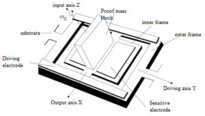
Figure 1 Schematic diagram of frame-type MEMS gyro
When alternating voltages with opposite phases are applied to the two excitation electrodes, the outer frame makes angular vibration motion around the driving axis due to the torque generated by the alternating electrostatic force, and at the same time, each point on the mass block makes linear vibration motion. When the base rotates around the input axis relative to the inertial space at an angular velocity of ω, each particle generates Coriolis acceleration and a Coriolis inertial force. This inertial force produces a Coriolis moment around the output axis. Under the action of this moment, The inner frame is caused to vibrate angularly around the output axis. The amplitude is proportional to the input angular velocity, and the phase depends on the direction of the input angular velocity. This causes the distance between the two reading electrodes and the inner frame to change according to a certain vibration rule, causing the capacitance to change. The output voltage signal can be calculated through the change in capacitance.
Error analysis of MEMS gyro
By analyzing the structure and working principle of the gyroscope, it can be seen that when it is working, various interference torques will be generated due to the friction of the inner and outer axes, electromagnetic interference, and the deviation of the center of mass of the gyroscope from the axis. These interference torques act on the gyroscope. Errors will occur. It can be seen that the error of the gyroscope is caused by the action of these interference torques, so the error of the gyroscope depends on the nature of the interference torque. The errors of gyroscopes generally include two categories: deterministic errors and random errors. Deterministic errors are regular and the numerical value can be determined through experimental methods. Random errors are caused by changes in the gyroscope's use environment, bearing noise, and temperature. Irregular errors cannot be compensated by simple methods.
In order to use mathematical expressions to describe the drift error variation pattern of MEMS gyroscope more accurately, the following models are usually used to describe:
1. Static drift error model:
Static drift errorωdis generated due to mass imbalance, various interference moments caused by unequal elasticity of the structure, and manufacturing processes. The expression is:
ωd=Kd+Kxax+Kyay+Kzaz+Kxyaxay+Kyzayaz+Kzxazax+Kxxax2+Kyyay2+Kzzaz2
In the formula:
Kd is the constant drift; Kx, Ky, Kz are the drift coefficients proportional to the specific force respectively; Kxx, Kyy, Kzz are the drift coefficients proportional to the square of the specific force respectively; Kxy, Kyz, Kzx are respectively The drift coefficient is proportional to the cross product of the specific force; ax, ay, and az are the specific forces along the corresponding axes of the gyroscope respectively.
2.Dynamic drift error model:
Dynamic drift error δωx is the error caused by angular velocity and angular acceleration under dynamic conditions. The expression is:
δωx=D’xώx+D’yώy+D’zώz+Dxωx+Dyωy+Dzωz+Dxyωxωy+Dyzωyωz+Dxzωxωz+Dxxωx2+Dyyωy2+Dzzωz2
In the formula:
D’x, D’y, D’z – angular acceleration error coefficient
Dx, Dy, Dz - calibration error coefficient
Dxx, Dyy, Dzz - angular velocity error coefficient
ώx, ώy, ώz - angular acceleration of each axis
ωx, ωy, ωz - angular velocity values of each axis
3.Random drift error model:
Random drift error has slow time variability and weak nonlinearity, which is difficult to describe with a specific mathematical model and can only be approximated by statistical characteristics. In the integrated navigation system, the random drift error is usually approximated as consisting of three parts: random constant drift, first-order Markov process and white noise. The expression is:
εi=εbi+εgi+ωgi
Error identification index of MEMS gyro
The system error of the MEMS gyroscope does not change with time, and is usually eliminated using experimental calibration and compensation methods. Random drift error changes with time and has great randomness and weak nonlinearity. It mainly includes quantization noise Q, angle random walk N, rate random walk K, bias instability Bs, rate slope R, etc., which can be identified by the Allan variance method, is the main factor affecting the accuracy of the gyroscope.
1. Quantization noise:
It is due to the error generated during A/D conversion of the collected data during gyroscope data collection. Its size is determined by the accuracy of the data acquisition system and has a very wide bandwidth. If the sampling speed is fast, the quantization noise generated will be very large, and measures need to be taken to suppress it. The formula is shown in Figure 2.
![]()
Figure 2 Quantization noise calculation formula
In the formula, Q is the quantization noise coefficient. In the Allan variance logarithmic plot, the value corresponding toτ= √3 on the straight line with slope k = -1 is the value of quantization noise.
2.Angle random walk:
Error caused by factors such as unstable excitation signal frequency, mechanical vibration, short correlation time, and external interference. The formula is shown in Figure 3.
![]()
Figure 3 Angle random walk calculation formula
In the formula, N is the angular random walk coefficient. In the Allan variance logarithmic plot, the value corresponding toτ=1 on the straight line with slope k = -0.5 is the value of the angular random walk.
3.Rate random walk:
The error caused by the integration of the broadband angular acceleration power spectrum density function is not clear yet. The formula is shown in Figure 4.
![]()
Figure 4 Rate random walk calculation formula
4.Bias instability:
It is an error caused by noise in the circuit, environment, etc., and has low-frequency characteristics. The formula is shown in Figure 5.
![]()
![]()
Figure 5 Bias instability calculation formula
In the formula, Bs is the coefficient of zero-bias instability, ƒ0 is the cut-off frequency, and C is the cosine function. In the Allan variance log-log plot, the value of the angular random walk is read on the straight line with slop k = 0.
5.Rate slope:
It is an error caused by electronic drift and unidirectional changes in the environment. It is a trend term of the data and behaves more like a deterministic error rather than a random error. The formula is shown in Figure 6.
![]()
Figure 6 Speed ramp calculation formula
In the formula, R is the coefficient of the rate slope. In the Allan variance logarithmic plot, the value corresponding to τ=√2 on the straight line with slope k >1 is the value of the rate slope.
Conclusion
In summary, we understand the error analysis and error identification indicators of MEMS gyros. MEMS gyroscopes will inevitably cause certain errors due to their own defects or the influence of environment, temperature, etc. This requires us to learn to identify errors through indicators and master error analysis method, so as to adopt reasonable calibration methods to suppress errors.
Ericco is engaged in the R&D and production of high-performance MEMS gyroscope, mainly for navigation-grade and tactical-grade MEMS gyroscopes. Through strict calibration methods, its errors are suppressed to a controllable range. For example, the ER-MG2-50/100, which is mainly used in ground navigation, has a bias instability of 0.01-0.02°/hr and an angular random walk of 0.0025-0.005°/√hr; tactical-grade high-performance MEMS gyros ER-MG-067, its bias instability <0.3°/hr, and angular random walk <0.125°/√hr.
If you are interested in other products and knowledge about MEMS gyroscope, please click on the products and articles below to continue learning.
More Technical Questions
1.Basic Knowledge of Bias Stability of MEMS Gyroscope
2.Error characteristic analysis of MEMS gyroscope
3.Development history of MEMS gyroscope
4.The materials and structure of MEMS gyroscope
5.How does MEMS gyroscope work in harsh high temperature environment?
6.MEMS Gyroscope: Error Compensation By Allan Variance Method
Products in Article


 High Performance Navigation Grade MEMS Gyroscope
 .jpg)