

Due to the defects in the production process and the influence of the external environment, there are various errors in the output of MEMS gyroscope. In order to improve the accuracy and robustness of the gyroscope output, it is necessary to calibrate the MEMS gyroscope before use to eliminate the influence of the error term on the sensor output. In this paper, the error characteristics of MEMS gyroscope are analyzed to help us better understand the various errors of MEMS gyroscope.
Scale factor error
Scale factor error refers to the deviation of the unit slope of the input-output of the inertial instrument after IMU unit conversion, and its schematic diagram is shown in Figure 1. The output error of a three-axis device caused by a scaling factor error is proportional to the true specific force along the sensitive axis.
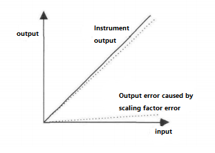
Figure1 Scale factor error diagram
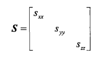
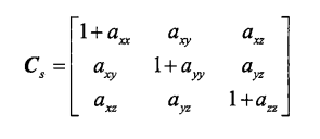
For a three-axis MEMS gyroscope, the scale factor error can be expressed as:
Non-orthogonality error
In various three-axis sensors, the non-orthogonality error is caused by the misalignment between the sensitive axis of the inertial sensor and the orthogonal axis of the carrier coordinate system. The essential cause of the misalignment between the shaft and the shaft is limited by the processing technology, as shown in Figure 2. Misalignment between axes causes each three-axis sensor to measure the specific force component in the direction orthogonal to its sensitive axis.
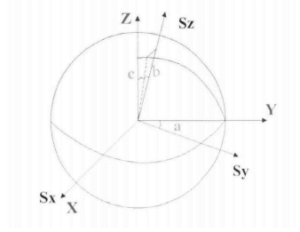
Figure2 Schematic diagram of non-orthogonality error
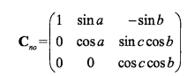
Where, Sx-Sy-Sz is the orthogonal coordinate system, X-Y-Z is the non-orthogonal coordinate system, a,b,c are the non-orthogonal error angles, and the non-orthogonal error can be expressed as:
Zero bias error
Zero bias is a constant error that all accelerometers and gyroscopes exhibit. Zero bias has nothing to do with the actual output of the carrier. Figure 3 graphically shows the relationship between sensor zero bias and input and output.
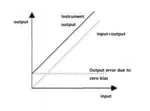
Figure 3 Relationship between zero bias and input/output
Hard magnetic error
The hard magnetic error is mainly caused by the induced magnetic field generated by the hard magnetic material or the magnetic field generated by the electronic device. The magnitude of the magnetic field intensity vector remains constant, and the direction relative to the carrier remains constant, resulting in a fixed shift in the magnetic field output.
Soft magnetic error
The soft magnetic error is caused by the induction of the ground magnetic field to the soft magnetic material of the carrier. The soft magnetic interference field is affected not only by the magnetic field vector but also by the angle between the carrier and the magnetic field vector. In a certain direction, the magnetization degree of the soft magnet is positively correlated with the external magnetic field, and the scale factor is mainly related to the properties of the soft magnetic material (such as permeability), so the relationship between the two is generally expressed by a linear relationship. The error coefficient can be set as shown in the following formula:
Misalignment error
The misalignment error refers to the attitude transition matrix between the inertial measurement unit coordinate system and the magnetometer coordinate system due to the production process or the printed circuit board (PCB board) mounting process.
Conclusion
This paper introduces some errors of MEMS gyroscope, which can help us distinguish the errors of MEMS gyro and take measures to reduce the errors. There are errors in MEMS gyroscope, but Ericco has done calibration work on every MEMS gyroscope delivered by the factory, and it is mainly for the middle and high-end precision market of navigation level and tactical level. For example, the navigation-grade MEMS gyroscope ER-MG2-50/100, a north-finding gyroscope, has zero bias instability of 0.01-0.02°/hr and an angular velocity random walk of 0.0025-0.005°/√hr. ER-MG-068 is a high-precision tactical gyro, which has the highest accuracy in tactical MEMS gyros, with zero bias instability of 0.3°/hr and angular velocity random walk of 0.125°/√hr.
If you are interested in other knowledge of MEMS gyroscope, please contact us.
More Technical Questions
1.Integrated method of three-axis MEMS gyroscope
2.Development history of MEMS gyroscope
3.MEMS gyroscope processing technology
4.Research on driving mode of MEMS gyroscope
5.Stochastic error modeling method of MEMS gyroscope
6.Signal Denoising Principle And Evaluation Index of MEMS Gyroscope
Products in Article
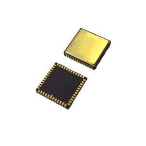
High precison MEMS Gyroscope
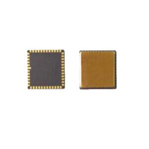


High Precision Stable-Control MEMS IMU