1. Electronic compass error classification
Electronic compass plays an important role in the navigation application of modern society, because electronic compass is based on the particularity of geomagnetic navigation, digital compass is prone to geomagnetic interference and magnetic material interference in actual use, resulting in measurement errors, according to the source of magnetic interference, can be divided into hard magnetic interference error and soft magnetic interference error. Among them, the hard magnetic interference will cause the zero deviation of the compass measurement value, which will lead to the inaccurate positioning of GPS in the navigation system. It will cause immeasurable impact on activities such as maritime navigation positioning and disaster rescue positioning. Moreover, compensation of hard magnetic interference error is a prerequisite for compensation of soft magnetic interference error. Therefore, before compensation of soft magnetic interference for electronic compass, it is necessary to ensure that the hard magnetic interference error has been compensated, so as to achieve a complete digital compass error compensation process.
2. Hard magnetic error analysis
In the actual working environment of electronic compass sensors, there are inevitably ferromagnetic materials, and one of these ferromagnetic materials is called hard magnetic materials. Because the hard magnetic material has the characteristics of high coercivity, it will be magnetized only in the external magnetic field with sufficient magnetic field strength. Although it is not easy to magnetize hard magnetic materials, the remanent magnetism after it is magnetized will be retained for a long time and is not easy to remove. The magnitude and direction of the magnetic field vector of hard iron in the carrier fixed coordinate system are fixed, and do not change with the course and position of the carrier.
Therefore, the error caused by hard magnetic interference is constant in the short term, which can be considered as a constant additional error output during calibration. At the same time, hard magnetic interference can be used to characterize all time-invariant perturbations of digital compass sensors without losing generality. In the actual measurement and use, the hard magnetic interference will cause the measurement value of the electronic compass to appear obvious deviation, that is, zero drift. In the ideal case of no hard magnetic interference, the electronic compass in the static state, rotating measurement one week, can draw a circle with the center at zero. The hard magnetic error causes the center of the circle to shift, which is called zero drift. Because of the particularity of the hard magnetic error, it can not be avoided and processed by simple physical means, but can only compensate the data collected by the compass to remove the hard magnetic interference error.
3. Hard magnetic interference error compensation method
3.1 Least square method
Generally, the constant error of the sensor is relatively stable, and the corresponding parameters can be obtained by calibration method, and the parameters are introduced into the error calibration equation. To eliminate the constant error of the sensor. Therefore, the error compensation method based on least square method can be adopted. As a kind of mathematical optimization technique, least square method can obtain the best matching function of the optimized object by minimizing the square of the error. Using least squares method can make it easier to obtain unknown data and minimize the sum of squares of error between the obtained data and the actual data. Least squares can also be used for curve fitting. The least square method is the most widely used method in system identification, which can be applied not only to dynamic systems, but also to static systems. It can be used to estimate linear and nonlinear systems as well as offline systems, and the online estimation of systems often uses least square method. In the random environment, when the least square method is used, the observation data does not need to provide its probability and statistics information, but the estimated results have quite good statistical characteristics. The least square method is easy to understand and master, and the recognition algorithm developed based on the least square principle is relatively simple to implement. When other parameter identification methods encounter difficulties, least square method can provide corresponding solutions. The most likely value of unknown model parameters is at the minimum of the sum of repeated error squares between the actual observed value and the calculated value, and the obtained model output can be closest to the output of the actual system, which is the principle of least square.
3.2 Algorithm simulation experiment
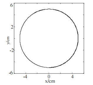
The Matlab editor produces a set of standard circle tracks whose center is not at the zero point of the coordinates. The center of the first standard circle is located at the coordinates (2,5) with a radius of 5, as shown in Figure 2. The center of the second standard circle is located at coordinates (114, -304), and the radius is also 5, as shown in Figure 3. It is assumed that the two standard circular trajectories are the actual trajectories measured by the digital compass under hard magnetic interference. Simulation experiments are carried out with the data to verify the feasibility of the algorithm.
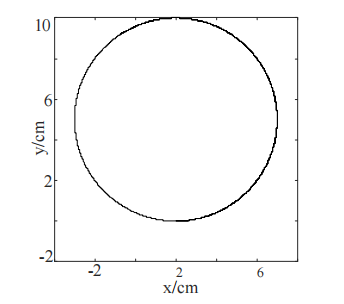
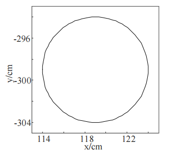
The experimental results are shown in FIG. 4 and 5 respectively. After zero deviation compensation, the zero drift of the standard circle is effectively compensated, and the center coordinates of the circle are located at (0,0) after compensation, and the trajectory does not deform. Moreover, good improvement is achieved in both large and small drifts. The simulation results show that the algorithm based on least square method is feasible.
4 Summary
We analyze the source of the hard magnetic error of the electronic compass, select the least square method as the error compensation method according to the error properties, and carry out the program design and simulation experiment based on the least square algorithm to verify the feasibility of the algorithm program. The feasibility and correctness of the algorithm in theory are verified, which lays a foundation for the actual measurement experiment. Ericco's E-compass products such as ER-EC-360A, ER-EC-365A and ER-EC-385CAN have hard magnetic, soft magnetic and inclination compensation functions, so we can use the least square method to compensate its hard magnetic interference error, so that the zero drift can be effectively compensated.
More Technical Questions
1.The Difference Between Gyroscope, Compass, IMU, MEMS
2.Application of Gyroscope in Electronic Compass
3.Principle of digital compass
4.What Is The Difference Between Gyro Error and Compass Error in Navigation?
5.How does an Electronic Compass Work?
6.Do You Know The Difference between electronic compass and GPS navigation?
Products in Article
