

MEMS gyroscopes have attracted global attention with their advantages of low cost, low power consumption, small size and batch production. However, for a long time, the performance of MEMS gyro has been hovering at the level of angular velocity applications. In recent years, with the improvement of micro-machining technology, micro-assembly and packaging technology, low noise analog IC chip design, control algorithm, and in-depth understanding of MEMS gyro error mechanism, there have been medium and high precision gyro prototypes and products have been reported. This paper aims to analyze a variety of typical MEMS gyroscopes with high performance, which will be described in terms of their structure, process and package.
Structure of high performance MEMS gyroscope
According to the motion mode of the micro gyro, the structure of MEMS gyros can be roughly divided into three types: torsional vibration gyro, line vibration gyro and ring gyro. At least one operating mode of the driving mode and the detecting mode of the torsional vibration gyro is torsional oscillation. The driving mode and detecting mode of the linear vibration gyro are both linear vibration. The Angle between the motion direction of the driving mode and the detecting mode of the ring gyro is 45 degrees. The three structures of the gyro are possible to achieve high precision.
1. Torsional vibration gyroscope
The first MEMS gyro, Draper Lab's internal and external gimbal gyro (shown in Figure 1), was a torsional vibration gyro. Coriolis effect causes the internal carnal joint to deflect vibration around the detection axis when the angular velocity perpendicular to the plane axis is input. The amplitude of vibration reflects the input angular velocity.
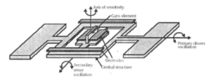
Figure 1 Draper Lab's double universal-joint gyro
In 1996, the alfalfa leaf MEMS gyroscope reported by Tong K. Tang of JPL Laboratory in the United States was shown in Figure 2. The stability of zero articles reported in 1999 was 1°/h, and that of zero articles reported in 2004 was 0.1°/h.
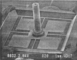
Figure 2 Four-blade micromachined gyroscope
In 1998, Geiger of HSV-IMIT in Germany reported the surface micromechanical wheel gyroscope, as shown in Figure 3, also known as RR gyroscope. The performance of RR prototype devices reported in the 2002 literature is as follows: RMS noise is 0.05°/s in 50Hz bandwidth under vacuum at 4 mbar and resolution is 0.005°/s.
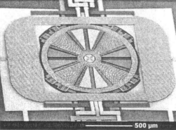
Figure 3 RR gyroscope of HSV-IMIT in Germany
In 2010, the butterfly gyro reported by Norwegian company SensoNor was a deflection vibrating gyro, as shown in Figure 4. The butterfly gyro adopts a tuning fork structure, and its driving and detecting modes are inverse-phase torsional vibration. The tuning fork structure helps to reduce the interference of axial acceleration.
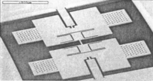
Figure 4 SensoNor's butterfly top
2. Line vibration gyroscope
The vibration of the driving mode and the detecting mode of the linear vibration gyro is translational, which is the most studied gyro type at present.
The first reported linear oscillating gyro was the comb-shaped tuning fork gyro from Draper Lab in 1993. Two mass blocks connected by flexible folding beams form a tuning fork structure. Under the action of electrostatic force, the two detection mass blocks move in reverse tuning fork mode along the drive axis X in the plane. When the angular velocity along the Z axis is input, the Coriolis effect will stimulate the reverse vibration of the two mass blocks in the Y direction, and the tuning fork structure helps to offset the interference of axial acceleration.
In 2008, Northop Grumman reported that the tuned tuning fork structure gyro belongs to the line vibration type gyro, as shown in Figure 5. The gyro is fabricated using a deep reactive ion etching process to obtain a large movable mass, and a vacuum of less than 0.03mbar is obtained by direct fusion bonding method of silicon. Through advanced analog and digital signal processing, the bias stability of the gyro is tested in batches to be less than 2°/h to 5°/h.
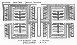
Figure 5 Diagram of Northop Grumman's tuning fork gyroscope structure
3. Ring top
The ring gyro was first reported in 1994 by Putty and Najafi of the University of Michigan, as shown in Figure 6. The main component of the gyroscope is a ring supported by some curved beams, and the middle of the ring is fixed. The ring vibrates in a plane driven by static electricity, and its vibration shape is elliptic. Any rotation around the axis will transfer energy to the second mode of motion, with the detection mode at a 45 degree Angle to the direction of the drive mode. The ring gyro structure is completely symmetrical, so the driving modes and detection modes match the other structures, and the structural symmetry minimizes the influence of temperature.
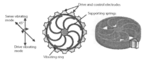
Figure 6 Structure diagram of the University of Michigan ring resonator gyroscope
Other typical ring-structured gyros include GIT's star resonator gyro, shown in Figure 7. A bias drift of 3.47°/h was reported in 2008.
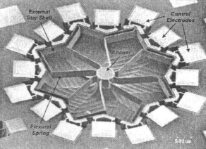
Figure 7 GIT star resonator gyro
Process and packaging
Traditional micromachining technology is mainly divided into surface micromachining technology and bulk silicon micromachining technology. Surface micromechanical process uses deposited film to fabricate microstructures, which is compatible with integrated circuit process and can realize monolithic integration of mechanical sensitive unit and processing circuit. The bulk silicon micromechanical process directly processes the matrix material to produce the quasi-three-dimensional structure.
With the development of micromanufacturing technology, many micromanufacturing processes integrate some processes of surface micromachinery and bulk silicon micromachinery, thus combining the advantages of both. More typical is the University of Michigan reported the high aspect ratio polycrystalline silicon and single silicon combination (HARPSS) process, which uses bulk silicon micromachining methods to obtain large movable mass blocks, and uses a technology similar to the sacrificial layer corrosion in surface micromachinery to obtain the fixed electrode and capacitor spacing. It combines the advantages of surface micromachining and bulk silicon micromachining.
At present, the mainstream process flow of high-performance MEMS gyro also has the advantages of surface micromechanical sacrificial layer corrosion process and bulk silicon micromechanical deep reactive ion etching process, and the more typical process flow is based on SOI wafer: the process flow is based on wafer bonding. Based on the process flow of SOI wafer, the gyroscope produced by this method has a thicker movable mass block, which can obtain a large movable mass and a small Brownian thermal noise base, so as to improve the performance of the gyroscope.
The low-cost SOI process developed by HG-IMIT is relatively typical, and the process flow is shown in Figure 8. (a) The AI electrode is machined on the structural layer on the SOI substrate. (b) Using PECVD deposited oxide layer, photoetching oxide layer, using oxide layer and photoresist as mask, deep reactive ion etching, and using anisotropic reactive ion etching process to carve the embedded oxide layer between the structural layer and the substrate. (c) PECVD deposition of the oxide layer is used again to protect the deeply etched trench side wall, and anisotropic reactive ion etching is used to carve the oxide layer between the structural layer and the substrate silicon. (d) Release of structures by isotropic silicon etching: In order to avoid electronic defects and reduce stress on the silicon and oxide layers, all oxide layers are removed by isotropic plasma etching processes. (e) A silicon-glass anode bonding is performed, using a bonded glass layer to protect the mechanical structure of the sensor from fine particles as well as dust and humidity during stroking.
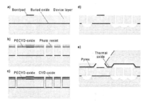
Figure 8 HSG-imit low-cost SOI process flow
The structure of Northrop Grumman's gyro is similar to that of the LL gyro, and the processing technology can sample the same process method. It should be noted that Northrop Grumman's gyro adopts silicon fusion bonding to carry out vacuum packaging. A stable vacuum has been obtained for many years.
The manufacturing process of GIT TFG gyro is very simple, and the process flow is shown in Figure 9. (a) Select the appropriate SOI chip. (b) On the back of the SOI film, the area below the moving area and the comb area is etched using a process developed by Bosch. (c) The oxide layer of SOI silicon wafer is etched by reactive ion etching. (d) Lithography on the front and release the structure.
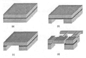
Figure 9 Process diagram of TFG gyro
The biggest advantage of wafer bonding is that a small movable gap can be obtained, and the movable structure can be protected for vacuum packaging. SensoNor's butterfly gyroscopes were successful because of the small capacitance gap and high vacuum achieved by using wafer bonding.
In addition, in order to improve the performance of MEMS gyros, it is often necessary to vacuum package MEMS gyros to improve the quality factor of MEMS gyro.
In order to improve the thermal environment of micro-mechanical MEMS gyroscope for detailed treatment, in 2009, the University of Michigan reported an on-chip temperature-controlled vacuum packaging technology. Through temperature control of the micro-mechanical gyroscope, as shown in Figure 10, the impact of environmental temperature changes on the performance of the gyroscope can be effectively reduced.
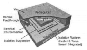
Figure 10 Temperature control structure of the University of Michigan
Sensor's SAR500, released in 2010, was also carefully designed in the package to reduce the impact of ASIC chip heat on the gyro. The packaging of the SAR500 watch head is shown in Figure 11. There is a metal layer under the chip, through which the heat is quickly dispersed. The metal cover plate is sealed by electron beam welding. The hybrid ASIC part is packaged in a separate ceramic shell with a large metal cooling base at the bottom of the ceramic shell.
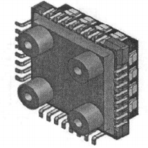
Figure 11 SensoNor's SAR500 assembly drawing
Conclusion
From the perspective of the structure of high-performance MEMS gyroscopes, MEMS gyroscopes of various structural forms have high-performance prototypes and products, indicating that the structure of MEMS gyroscopes is not intrinsically good or bad, and the performance of MEMS gyroscopes does not depend on the structural form, and high performance can be achieved if it is done well.
From the perspective of process flow, the hybrid process with the advantages of composite silicon micromachining and surface micromachining has become the mainstream of high-performance MEMS gyroscope machining process. Large mass blocks can be obtained by bulk silicon process and small capacitance gaps can be obtained by surface micromechanical sacrificial layer corrosion: In order to improve the precision of MEMS gyros, MEMS gyro often needs vacuum packaging to improve the quality factor, and careful design and treatment of the thermal environment of MEMS gyro head is also necessary for high performance gyro.
As an expert in the development and production of navigational and tactical MEMS gyroscopes, Ericco has conducted in-depth research on its structure and process, such as the use of silicon as raw materials and the use of vacuum ceramic packaging technology, especially ER-MG2-50/100 and ER-MG2-069, which are representatives of navigational and tactical MEMS gyros respectively. Its precision level and performance are excellent.
I hope that through this article you can understand the knowledge of MEMS gyroscopes, if you want to know more content, please click the related products and articles below.
More Technical Questions
1.The impact of turntable error on MEMS gyroscope calibration
2.The analysis of damping in MEMS gyroscope
3.Error Analysis of MEMS Gyroscope
4.Noise Analysis and Solutions of MEMS Gyroscope
5.Wafer-level vacuum packaging of MEMS gyroscope chips
6.The materials and structure of MEMS gyroscope
Products in Article


.jpg)