MEMS gyroscope is micromechanical gyroscope that measure angular rate based on the Coriolis force. They are used in a wide range of applications, such as north seeking, navigation, positioning and orientation, etc. The full name of MEMS is micro mechanical system. In recent years, the accuracy level of MEMS gyroscopes has improved rapidly, with obvious advantages, and it has become the choice of many industries. However, no device is perfect, and MEMS gyros also have their own flaws. Noise is one of them. In order to minimize the impact of defects on accuracy, corresponding compensation methods are needed to deal with the occurrence of defects. This article aims to analyse the causes and solutions of noise problems.
The following will analyze the causes of noise, Allan variance, noise sources and solutions.
Causes of noise
If a MEMS gyro wants to achieve functions such as north seeking and navigation, the most critical aspect is its accuracy. MEMS gyroscopes are made using semiconductor processing technology and are made of silicon. The components of MEMS gyroscope may have noise, causing random noise during the measurement process, and many environmental factors may also cause noise, instability, drift and other phenomena, ultimately affecting the measurement accuracy of the MEMS gyroscopes.
The principle of Allan variance
Allan variance is a method for analysing MEMS gyroscope noise sources. Before understanding the noise sources of MEMS gyros, we need to first understand the basic principles of Allan variance.
Allan variance is a frequency domain analysis technique proposed by David Allan in 1966. It is an IEEE recognized method for describing gyro noise and stability. The principle is to describe various noise sources through the different characteristics exhibited by the variances in different correlation times. It is a method of analysing time series and extracting the inherent clock noise from the system as an average time function. This is applicable to research of the noise of any system.
According to the 1984 world geodetic coordinate system, the earth's rotation rate is approximately 7.2921×10⁻⁵ rad/s, which is approximately 15.0411°/h. To measure such a low rotational speed or even smaller rotational speed, the accuracy of the gyroscope is very high. Perform Allan variance analysis on the static output of the MEMS gyro to obtain the error level of the MEMS gyroscope. The main error indicators of MEMS gyroscopes include bias instability, angular random walk, etc.
Suppose the gyro sample length is N and the sampling period is T. Divide the samples into several groups, the number of samples in each group is m, and average the data of each group. Therefore, the average angular velocity within the time of tk and tk+τ is:
![]()
The Allan variance estimate for MEMS gyro data is:
![]()
Allan variance is obtained by different τ, the fitting coefficient is obtained by least square method, and then the noise coefficient is obtained.
MEMS gyroscopes noise source
MEMS gyroscope is mainly caused by the following noise sources:
1. Angular random walk
There are many sources of this noise, such as external interference, high-frequency noise, etc. This noise has the characteristics of an angular rate white noise power spectrum.
2. Bias instability
When the gyro angular rate fluctuates at low frequencies, it will cause bias instability, which is mainly caused by the gyro's own factors, such as circuit component noise, ambient temperature, parasitic effects between devices, etc.
3. Rate random walk
The source of this noise cannot be determined exactly, but it can be obtained by integrating based on the broadband angular acceleration rate, to which MEMS gyroscopes and laser gyroscopes are more sensitive.
4. Quantization noise
Quantization noise will be generated during the digital-to-analog conversion of the sensor output, which is a white noise sequence. Its correlation time is short, and broadband noise can be processed using a low-pass filter.
5. Rate ramp
Rate slope, as the trend term noise in MEMS gyroscopes, is a deterministic error caused by circuit noise, environmental conditions, etc.
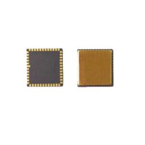
In order to improve the accuracy of MEMS gyros and calibrate the errors caused by them, Ericco continues to develop and produce MEMS gyros with excellent performance. As a high-performance north-seeking gyro, ER-MG2-50/100 has a bias instability of 0.01-0.02 deg/hr, an angular velocity random walk of 0.0025-0.005 °/√h, and a noise peak of ±0.002-±0.003 deg/s.
Solution - wavelet filtering
Since there is a lot of interference noise in the gyro output, directly using noisy data in the system will affect the system performance. Wavelet filtering has the characteristics of multi-resolution analysis in signal processing, and can distinguish non-stationary and stationary signals in the signal. It has strong denoising ability for non-stationary signals and good signal denoising effect. Therefore, we will introduce how wavelet filtering is used to filter out the random noise of MEMS gyrosscope.
By setting up high-pass and low-pass filters, wavelet filtering first decomposes the sensor signal into high-frequency and low-frequency components through these two filters, and then continues to decompose the low-frequency component obtained from each decomposition to achieve multi-scale decomposition of the sensor signal. For the purpose of multi-scale decomposition of the original signal, the effect depends on the wavelet base, number of decomposition layers, threshold selection and threshold function.
The mathematical model of wavelet filtering is as follows:
w(k)=ƒ(k)+e·ε(k) k=0,1,...,n-1
Among them,
w(k) is the original signal of MEMS gyro
ƒ(k) is an unbiased signal
e is the standard deviation of the noise figure
ε(k) is noise
According to the experimental data, we collected the MEMS gyroscope static angular rate data of the Y-axis and Z-axis for 2 hours and performed wavelet filtering processing. The comparison is as follows:
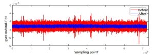
Figure 1 Comparison before and after Y-axis MEMS gyro filtering
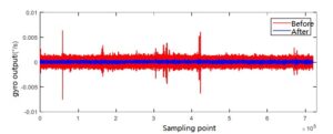
Figure 2 Comparison before and after Z-axis MEMS gyro filtering
As can be seen from the above figure, after wavelet filtering, the MEMS gyro output angular rate amplitude is significantly reduced, and some sudden noise is filtered out, and noise interference is significantly suppressed. As one of the noise solutions, wavelet filtering is an effective way to suppress noise interference.
Through this article, I hope you can gain some knowledge about MEMS gyro noise. If you are interested in other contents of MEMS gyroscope, you can click on the related products and related articles below to continue learning.
More Technical Questions
1.How does MEMS gyroscope work in harsh high temperature environment?
2.What’s the north-seeking principle of MEMS gyroscope?
3.Basic Knowledge of Bias Stability of MEMS Gyroscope
4.Signal Denoising Principle And Evaluation Index of MEMS Gyroscope
5.Classification And Performance Improvement Of MEMS Gyroscope
6.MEMS Gyroscope: The Third Generation Of Gyroscopes Is Leading The Way
Products in Article