Aiming at the problems of high calibration cost and strict requirement of northbound datum in traditional calibration methods, a calibration method of the flying attitude system of fiber optic gyro (GYRO) with single-axis speed turntable as calibration equipment was proposed. The error of the combination of Fiber-optic gyro was modeled, and the three gyros of the Fiber-optic gyro JiG attitude system were mounted on the single-axis speed turntable. The three gyros were calibrated with their axes facing down respectively. The 12 error parameters of zero deviation, scale factor and installation misalignment Angle were calibrated. Through the analysis of calibration accuracy, the feasibility of the method is verified. The calibration cost is low and the northbound reference is not required, so it has certain engineering application value.
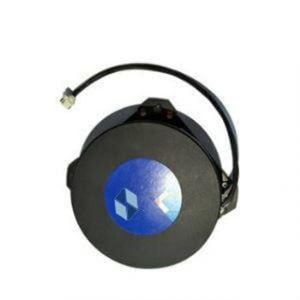
Fiber optic gyro is the main component of optical fiber strapdown inertial navigation system. It is a photoelectric inertial sensor developed based on Sagnac effect. As an angular velocity sensor, it has obvious advantages in performance, such as high sensitivity, high precision, high reliability, large dynamic range, insensitive to acceleration and vibration, and compact structure. It is an ideal sensor for a new generation of strapdown inertial navigation system. Therefore, fiber optic gyro has been widely used in inertial navigation field in recent years. The ER-FOG-50 miniature fiber optic gyro is an important angular rate sensor, which has the characteristics of long life, fast start-up, high precision, low power consumption and wide dynamic range. It also plays an important role in aerospace, weapon navigation, platform stabilizers, drones and other fields.
In order to improve the accuracy of inertial navigation system, it is usually necessary to calibrate it. Calibration technology is a method to improve the actual accuracy of inertial navigation system from the aspect of software, and it is also an error compensation technology in essence. The so-called error compensation technology is to establish the error mathematical model of inertial device and inertial navigation system, determine the model coefficient through a certain test, and then eliminate the error through software algorithm. The calibration of inertial navigation system (INS) is the premise of inertial navigation, and the calibration result will directly affect the accuracy of inertial navigation.
Under the condition of constant instrument hardware, the system accuracy after error compensation will be significantly improved. It is an effective means to improve the navigation accuracy of inertial navigation system to calibrate the inertial navigation system regularly and correct the measurement error of inertial components.
Error model of fiber optic gyro strapdown attitude system
The attitude system is composed of three fiber optic gyroscopes, and the error of a single fiber optic gyroscope is also the object of calibration. The output of the instrument has a proportional relationship with the measured true value, which is called the scale factor. When the measured true value is zero, the output of the instrument is not zero, which is called zero bias. By analyzing the error characteristics of three FIber-optic gyroscopes, the parameters to be calibrated mainly include misalignment Angle, scale factor error and zero deviation.
Calibration method
The essence of calibration is the acquisition of misalignment Angle, scale factor and zero deviation. The measurement data of inertial devices are compensated by calibration parameters and then navigation is solved to improve navigation accuracy.
Firstly, the fiber optic gyro (GYRO) jet attitude system is installed on the surface of the single-axis speed turntable by means of tooling. The sensitive axis of the axis gyro is perpendicular to the table surface, and then the number of gyros is statically collected. Finally, the single-axis speed turntable is controlled to rotate forward n times at a certain speed to collect the data of the gyro, and the single-axis speed turntable is controlled to reverse n times at the same speed to collect the data of the gyro.
Discussion on the influence of turntable error on calibration accuracy
The position accuracy of the turntable will have a certain impact on the calibration accuracy. The influence of the position accuracy of the turntable on the calibration accuracy of the gyroscope scale factor and the installation error is d / 2nπ(d is the position accuracy of the turntable)
In the case of fiber optic gyro, the calibration error caused by the position accuracy of the turntable can be ignored. In the rotating process of the turntable, there may be uneven rotation speed. At this time, the horizontal component of the earth's angular velocity can not be completely eliminated in the calibration process, which has a certain impact on the calibration result, but for the general turntable, the impact is small and can be ignored.
Fault handling
Fault classification and handling measures:
Class I fault:
Class I fault is an irreversible failure caused by the power supply or control closed loop of the turntable, which is not directly caused by the turntable itself and does not require maintenance, mainly including power failure, control divergence, movement overrun, etc. The turntable operator should make a preliminary fault judgment according to the fault phenomenon, and when the fault criteria are met, the turntable should be stopped immediately and the power supply should be disconnected. After the external fault is completely eliminated, the operator can determine whether to continue using the turntable, as shown in the following table.
| Fault type | Fault Symptom | Fault Diagnosis Methods | Solutions |
| Main power failure | Limit over-voltage or undervoltage of the power supply | Voltage monitoring exception | The turntable stops working, disconnect the power supply, and continue to power on after the power failure is completely eliminated |
| Control power failure | Limit overvoltage or undervoltage of the power supply | Voltage monitoring exception | |
| Power failure | Abnormal power supply system | The turntable power indicator is off | |
| Drive overcurrent, overload | The output current of the driver exceeds the allowable running time of the peak current, and the turntable shafting is not out of control | Driver fault feedback signal | Stop the turntable, check whether the load is overloaded, whether the load is seriously unbalanced, and there is external resistance in the shafting, and continue to power on after the external fault is completely eliminated |
| Driver failure | Drive overheating, turntable shafting is not out of control | Touch the driver housing with your hand and the driver temperature exceeds the permissible temperature limit | |
| Control divergence | The system error diverges and exceeds the allowable value | The system collects and compares the Angle signal, and prompts the fault code | |
| Motion overlimit | Motion shafting over limit, over speed, over acceleration, etc | The system compares the acquisition of Angle, speed and acceleration with the maximum allowed value, and prompts the fault code | The turntable stops working. Check whether the turntable command input exceeds the set value |
Class II failure:
Class II failure refers to the faults that can affect the performance indicators of the turntable system and need to be corrected by the turntable maintenance personnel, mainly including power failure, drive failure, motion overrun, Angle measurement failure, motor failure, etc. The turntable operator should make a preliminary fault judgment according to the fault phenomenon, and eliminate Class I faults and Class III faults. When the fault phenomenon meets the fault criteria, it should be stopped immediately and the power supply should be cut off. After the fault is completely removed, the operator can continue to use the turntable, as shown in the following table.
| Fault type | Fault Symptom | Fault Diagnosis Methods | Solutions |
| Power failure | The power supply cannot be powered on | The power supply voltage of the measurement line is normal and cannot be powered on | Troubleshooting Class I faults, Class III faults, professional troubleshooting |
| Angle fault | Rotating table shafting runs out of control or shafting cannot operate | After disconnecting the enable function, rotate shafting manually and check that the measurement Angle has no feedback or is inconsistent with the rotation Angle | Troubleshoot Class I faults, Class III faults |
| Goniophotometer Sensor Failure | Rotating table shafting runs out of control or shafting cannot operate | Use oscilloscope to measure sensor input and output signals, input is normal, output is abnormal | Professional troubleshooting |
| Driver failure | Drive overheating, drive alarm, shafting is not working | Touch the driver housing with your hand, the driver temperature exceeds the allowable temperature limit, and the driver flashes the fault code | Professional troubleshooting |
| Drive overcurrent, shafting running out of control | The power-on status of the driver is normal, and the measured DA value of the driver is abnormal when the shafting does not close the loop | Professional troubleshooting | |
| The driver status indicator is off after the power-on | Measure the driver control power supply voltage after power-on. If the voltage is normal, the driver is faulty | Professional troubleshooting | |
| Motor fault | Turntable shafting does not work or does not work according to the given command | The motor resistance is abnormal, and the motor has a burnt odor | Professional troubleshooting |
Class III faults refer to general operation errors, which can be removed by the operator on the premise of safe operation, as shown in the following table.
| Fault type | Fault Symptom | Fault Diagnosis Methods | Solutions |
| The power supply neutral wiring is faulty | During power startup, the contactor makes a continuous sucking and disconnecting sound. | The main contactor used for power on/off, the contactor can not be absorbed normally, the power supply is abnormal. | Check whether the power supply is normal and whether the neutral wire is loose |
| Power start failure | Pressing the Start button fails to power on | The power supply is normal after the button is pressed, and the power supply is disconnected after the button is released | Check whether the main power switch on the panel of the control cabinet is turned on.
Or check whether the emergency Stop knob is turned on, and then power it on again. |
| Drive power supply failure | After normal power-on, all or one shafting of the turntable cannot run | The system reports "out of tolerance", the driver control power is normal | Check that the motor cable or signal cable is not connected. The power supply of the corresponding shafting in the control cabinet or power cabinet is cut off. The component involved may be an air switch or circuit breaker. The operator can close the air switch or circuit breaker again.
Connect the unconnected cable properly |
| The line is not connected | Shafting running out of control or not running | Check line connections, especially signal feedback cables and motor cables | Connect the unconnected cable properly |
| The line is not connected | software interface indicates input error | Determine whether the input exceeds the turntable setting value | Enter a reasonable parameter again |
| Procedure operation error | The software displays an error sequence | Determine whether the operation sequence is combined with the turntable setting sequence | Re-operate the turntable in a reasonable sequence |
More Technical Questions
1.Development Trend of Single-axis Turntable in our Country
2.The Internal Structure Characteristics of the Two-axis Turntable
3.The Main Structure of the Single Axis Turntable
Products in Article