With the development of inertial technology, strap-down north finder has become the main trend of development because of its speed, high reliability, no need to provide geographical location information and simple structure. North finder plays an important role in military applications such as missile launching and artillery aiming. In practical engineering applications, the operating latitude of the north finder is from 53° South to 53° north. In the range of Earth latitude 0° ~ 53°, the north component of the earth's rotation angular velocity varies greatly, and the amplitude of the gyroscope output signal will have a large difference. When the sampling resistance of the signal acquisition system is fixed, the gyro data fitting curves are different in different geographical latitudes, and some geographical latitude data fitting curves will lead to data loss, which will have a certain impact on north finding.
1.The overall design of strap-downnorth finding system
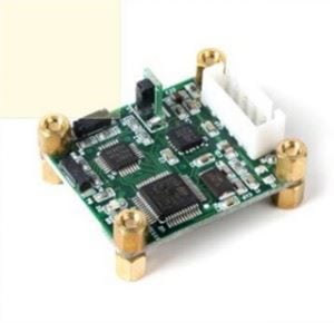
The strap-down north seeking system is composed of data acquisition and processing system, turntable leveling system (inclinometer), rotation control system (servo unit), inertial measurement system (fiber optic gyro and accelerometer), temperature control system (temperature control unit), etc. The data acquisition and processing system is composed of signal acquisition module, signal processing module, data display module and data communication module, which is the central processing core of the north finder, mainly realizing the function of data acquisition and processing and calculating the north seeking angle. The signal acquisition module converts the current signal output by the gyro into voltage signal, and then converts it into digital signal through A/D. The signal processing module performs digital filtering on the gyro data, processes the gyro data and encoder data of multiple transposition positions, and calculates the north seeking angle. The data display module displays the working state and north seeking angle data of the north finder; Data communication module communicates with servo control unit, temperature control unit, electronic inclinometer, encoder and host computer through serial port, and sends and receives data.
2.Fiber optic gyroscope data acquisition
The fiber optic gyro adopts differential pulse output mode. The output of each gyro consists of positive and negative pulses. The pulse frequency varies with the carrier's angular velocity. The range is 0~2MHZ and the pulse width is 250ns. How to ensure that the pulse is not lost is very important, so the design of high frequency and reliable pulse counting to count the output pulse of the gyroscope, in order to prevent the interference of the peak jitter pulse, the gyro pulse is firstly filtered and shaped in the front end of the pulse counter module, and then the level frequency doubling sampling is adopted, because the sampling triggered by the pulse rising edge or falling edge will produce false triggering, and the reliability is low.
The update frequency of IMU data in the north finder is 100 Hz, that is, the gyroscope data sampling period is 10ms. When the 10ms interrupt signal rises, the positive and negative counters will be subtraction to obtain the gyroscope data. The result will be temporarily stored in the register, and the counter will be cleared to zero to start the next count. The gyro data in the register is sent to the data RAM for DSP reading when the 10ms interrupt signal falls along the edge. In addition, in order to improve sampling accuracy of the system, oversampling technology is adopted during sampling, that is, a large number of gyro data are collected within each sampling period, and then used for azimuth solution after smoothing and filtering.
In order to verify the correctness and reliability of the design of the pulse counter, a signal generator is used to generate pulse signals, which are connected to the pulse acquisition port of the data acquisition unit, the number of pulses generated by the signal generator is collected in a fixed period of time, and sent to the computer through the serial port. The experimental results are shown in Table 1, where the pulse width is 80ns, the amplitude is 3.3V, and the sampling time is 10ms.
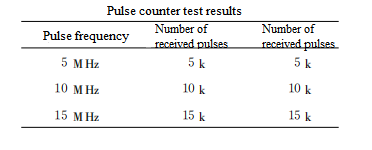
It can be seen from the measurement diagram that the number of pulses sent by the signal generator and the number of pulses collected 1 verify the correctness of the design of the pulse counter. The output of the accelerometer is converted into A pulse signal after A/D conversion, which is similar to the gyroscope data acquisition, and will not be repeated.
3.Serial port expansion
The IMU and attitude data need to be sent to the upper control microcomputer through the serial port. The DSP chip in this system has only one synchronous serial port, so it is necessary to design an asynchronous serial port. For the extension of DSP synchronous to asynchronous serial port, the traditional method is to use special asynchronous communication devices to achieve. Based on the abundant I/O resources of FPGA, this paper uses Verilog language to describe UART and realize the conversion of synchronous and asynchronous protocols, which not only simplifies the hardware circuit but also reduces the burden of DSP. At the same time, using FPGA to design the serial port can reduce the cost and volume of the system and has the advantages of easy transplantation and upgrading.
Conclusion
From the perspective of practical application, this paper introduces the system design in detail, aiming at the requirement of real-time, reliability and precision, multi-channel data acquisition unit of north seeker. Based on the data acquisition technology of north seeker, Ericco continues to improve its own technology, if you are interested, welcome to check our specific products, among which ER-FNS-03 solves the expensive characteristics of traditional FOG north finder with the advantage of low cost, ER-MNS-05 and ER-MNS-06 combine with MEMS technology, manufacture a small medium and high precision north finder, welcome to your understanding.
More Technical Questions
1.Effective combination of north finder and spacecraft based on autonomous orientation
2.Research on downhole north seeker
3.Research on orthogonal monitoring technology of north finder
4.Modeling and filtering in signals collected by FOG north seekers
5.Error Modeling and Compensation Analysis of North Finder Based on FFT
6.Research and use of north finder for mining drilling rigs
Products in Article