Digital compass (also known as electronic compass) is a device that uses geomagnetic measurement principles to determine direction. The three-axis digital compass can provide the carrier's heading angle and attitude angle in real time, and compensate the inclination when the compass tilts to ensure the accuracy of the heading data. With the development of sensor and semiconductor technology, electronic compass has realized miniaturization and low power consumption, and has been widely used in aviation, navigation, land transportation, field exploration and other fields, and is an indispensable part of modern directional navigation system.
The accuracy of the digital compass is determined by the magnetic sensitive element for measuring the geomagnetic field. According to the different working principles of the magnetic sensor used, the commonly used electronic compasses mainly include Hall effect electronic compass, magnetic induction electronic compass, flux-gate electronic compass and magnetoresistive electronic compass. Compared with the above sensors, the magnetoresistive sensor has the advantages of small size, low power consumption and high measurement accuracy, but the disadvantage is poor stability, and the corresponding compensation method needs to be taken to eliminate the influence of external magnetic field and temperature drift, and finally meet the design requirements.
1.Solution of three-axis digital compass attitude angle
The definition of the attitude angle of the digital compass is shown in Figure 1. The magnetic field intensity Hxb, Hyb, and Hzb in the three axes measured by the magnetic sensor are measured under the carrier coordinate system OXbYbZb, and their projections under the navigation coordinate system (geography system) are Hxn, Hyn, and Hzn. N-S represents the Earth's north-south axis, N '-S' represents the geomagnetic north-south axis, and the included angle β is called the magnetic declination Angle. ϕ is the Angle between projected Hny in the geographic coordinate system and the local magnetic meridian in the direction of advance. The pitch angle θ is the angle between the Y-axis of the carrier coordinate system and its projection on the navigation coordinate system, and the roll angle γ is the angle between the X-axis of the carrier coordinate system and its projection on the navigation coordinate system. In this paper, the pitch angle θ and roll Angle γ are calculated from the output of the accelerometer.
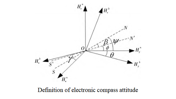
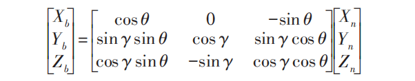
The heading angle is defined as the angle between the carrier coordinate system and the navigation coordinate system. To solve the heading angle in the navigation coordinate system, the measured value of the magnetic sensor in the carrier coordinate system must be transformed to the navigation coordinate system through the geomagnetic field coordinate transformation. The navigation coordinate system is set to be completely consistent with the carrier coordinate system at the beginning, and the navigation coordinate system moves with the carrier coordinate system. If the carrier movement causes the navigation coordinate system to rotate angle θ to OXbYbZb around the Yb axis of the carrier coordinate system, and then roll angle γ around the Xb axis, the coordinate transformation relationship between the carrier coordinate system and the navigation coordinate system can be expressed by equation (1)
2. Error compensation
The digital compass uses the magnetic sensor to measure the geomagnetic field to determine the direction, and the noise of the power supply and the ground wire, the manufacturing error of the magnetic sensor and the assembly error will affect the measurement accuracy. The interference of the external environment to the electronic compass can be suppressed and the measurement error can be reduced by means of hardware filtering, circuit routing optimization, power supply noise reduction and software data processing. The superposition of environmental magnetic fields such as ferromagnetic materials and electrical equipment near the magnetic sensor with the earth's magnetic field will cause the magnetic sensor to be difficult to correctly sense the Earth's magnetic field, resulting in a larger heading error. Compass error is the most important factor affecting the accuracy of magnetic compass, so it needs to be corrected. Both hard magnetic materials and soft magnetic materials will cause compass error. Considering the hard magnetic compass error and soft magnetic drop comprehensively, the formula for calculating compass error can be obtained as follows
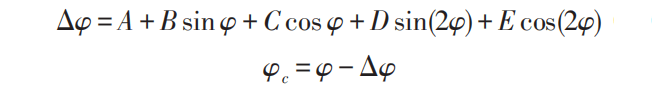
φ is the heading angle before the deviation compensation, Δφ is the total deviation, and φc is the true heading Angle after the deviation compensation. A, B, C, D and E are compass compensation coefficients, and the least squares 36 position method is used to solve the compass compensation coefficients. The equation for calculating the compensation coefficient of compass difference is as follows
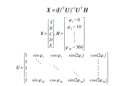
In the process of error compensation, the electronic compass is fixed on the non-magnetic carrier and rotated 360°, the original heading value is collected every 10°, and the compensation coefficient X of the compass difference can be solved by substituting the measured data into equation (3). When the electronic compass is working, the compensation coefficient can be brought into the formula (1) and (2) to obtain the course angle of the compensated electronic compass. Combining the local magnetic declination angle, the geographical course angle in the geographical coordinate system can be further calculated. Under the premise of not losing the generality, the magnetic declination angle is not considered in this paper, and the calculation results of the electronic compass are analyzed as the heading angle.
Conclusion
Ericco technicians have studied the attitude angle solution and error compensation of the three-axis electronic compass, which can reduce the interference of the environment to the digital compass and reduce the measurement error to a certain extent. The research method indeed has certain reference value for the measurement accuracy of the digital compass. If you are interested in our electronic compass ER-EC-360A, ER-EC-360V,please learn more about the specific parameters.
More Technical Questions
1.Research on temperature compensation technology of 3D electronic compass
2.Electronic compass dynamic heading error correction
3.Soft Magnetic Error Compensation Method of Electronic Compass
4.Electronic Compass Hard Magnetic Error Compensation
5.Application of Gyroscope in Electronic Compass
6.Principle of digital compass
Products in Article