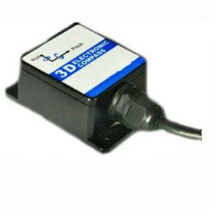
Electronic compass is widely used in attitude measurement because of its advantages of low cost, low power consumption, small size and easy interface with digital processor. It can be used not only for a variety of manned and unmanned land, air and water equipment platforms, but also for a variety of consumer electronics products. Three-dimensional digital compass based on three-axis accelerometer and three-axis magnetic sensor can realize magnetic north Angle measurement under different attitude by sensing gravity field and geomagnetic field.
Although the performance of accelerometers and magnetic sensors has been significantly improved with the advancement of microelectromechanical system technology, errors caused by inconsistent sensitivity coefficients, non-orthogonality, bias, and unique characteristics of magnetic sensors will still be introduced during sensor production and installation. Soft and hard magnetic interference errors cause the original output of the three-axis sensor to be inconsistent with the three components on the coordinate axes of the body coordinate system. Therefore, in order to obtain high-precision attitude information, digital compass still needs to be calibrated and compensated before use.
1.Electronic compass error compensation methods
At present, the research on digital compass error compensation methods is based on whether to use an external reference. The calibration methods of three-axis sensors can be divided into two categories. The first category is: collecting high-precision turntables or direction positioning blocks to provide measurement values at specific attitude reference points for mathematical processing, determining parameters in the error model, and achieving error elimination. The second category is: using the characteristic that the module of the geomagnetic field vector and the gravity field vector is a constant, combined with the Possion error model, and fitting a large number of collected data points to an ellipsoid surface based on certain mathematical methods to determine the error model Relevant parameters to achieve sensor calibration. The above two types of methods have achieved good results in eliminating or reducing errors, giving the electronic compass a higher magnetic north angle accuracy. However, the above calibration method is less concerned with the temperature drift problem of the digital compass. Considering that the characteristics of the acceleration sensor and magnetic sensor that make up the electronic compass are closely related to temperature, it is necessary to consider the temperature compensation of the digital compass when performing error calibration.
Based on the analysis of the error model and calibration method of the three-axis sensor, the corresponding temperature compensation method is proposed, which realizes the temperature compensation of the sensitivity coefficient and bias of the three-axis sensor, and finally improves the ambient temperature adaptability of the three-dimensional digital compass.
2.Three-dimensional electronic compass hardware design
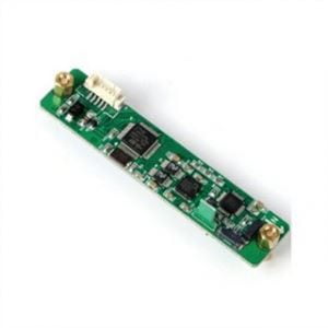
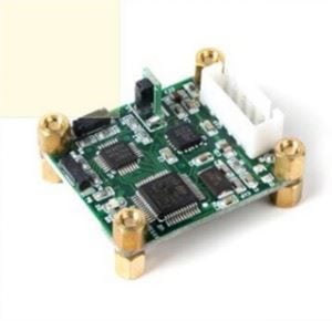
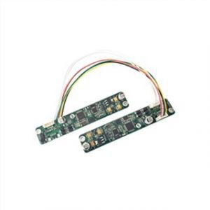
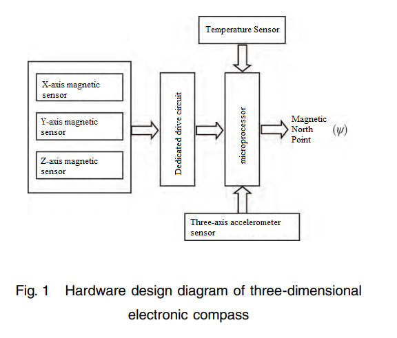
The three-dimensional digital compass is mainly composed of a three-axis acceleration sensor, three discrete magnetic sensors, temperature sensors and a microprocessor, and its hardware design is shown in Figure 1.
3.Three-axis vector field sensor temperature compensation model
For three-axis vector field sensors, various errors such as sensitivity inconsistency, non-orthogonal three-axis, and zero offset are inevitable during the manufacturing and installation processes. At the same time, since the material properties and signal processing circuit properties of the sensor are closely related to temperature, the sensor signal has a temperature drift. For this reason, the classic Possion model of the three-axis vector field sensor error that describes the above error needs to consider the influence of temperature while neglecting the nonlinear error of the sensor.
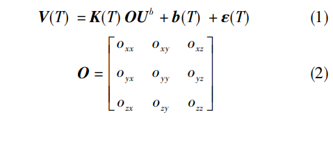
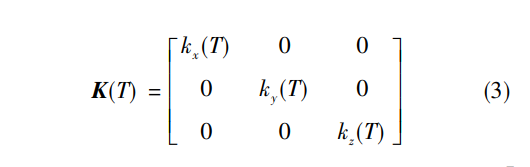
In formula (1) ~ (3), V(T) = [Vx(T)Vy(T)Vz(T)]T is the output of the three axes of the sensor when the temperature is T; The diagonal matrix K(T) is associated with inconsistent sensor sensitivity. O is the correlation term describing the non-orthogonal sensitive axis of the sensor, considering that its geometric characteristics are less affected by temperature, it can be regarded as a constant; b(T) = [bx(T)by(T)bz(T)]T is the zero bias of the sensor; ε(T) = [εx(T)εy(T)εz(T)]T is the measurement noise of the sensor, which can generally be eliminated by averaging several consecutive measurements at each measurement point. For the three-axis magnetic sensor, there is also an error caused by soft and hard magnetic interference, in which the soft magnetic interference can be included in O, and the hard magnetic interference can be included in b. Therefore, from a mathematical point of view, the error model of both the three-axis acceleration sensor and the three-axis magnetic sensor can be described by equation (1).
4.Summary
With the rapid development of miniaturization, unmanned platforms and various intelligent devices, the demand for low-cost, low-power, small-size and high-precision attitude measurement technology is becoming more and more extensive. The influence of temperature on the characteristics of the acceleration sensor and magnetic sensor of the three-dimensional digital compass leads to the temperature degradation of the magnetic north Angle accuracy of its output. In this paper, the corresponding temperature compensation method is proposed for the error model, and the temperature compensation for the sensitivity coefficient and bias of the three-axis sensor is realized, and the ambient temperature adaptability of the three-dimensional electronic compass is finally improved. In Ericco company, ER-EC-360A, ER-EC-360B also improve their environmental temperature adaptability, if you are interested in electronic compass, welcome to see our specific product parameters.
More Technical Questions
1.Electronic compass dynamic heading error correction
2.Soft Magnetic Error Compensation Method of Electronic Compass
3.Electronic Compass Hard Magnetic Error Compensation
4.Application of Gyroscope in Electronic Compass
5.Principle of digital compass
6.What Is The Difference Between Gyro Error and Compass Error in Navigation?
Products in Article