MEMS gyroscope is a new technology in the 21st century, which is widely used in various fields, and its status in the field of oil and gas is gradually improving. With the deepening of oil and gas exploration and development, the geological conditions faced by drilling and completion engineering become more and more complicated. Most downhole MWD tools are mainly used for single dimension measurement near the bit, and they cannot measure the physical parameters such as downhole temperature and pressure in the whole wellbore. In order to solve this problem, micro-measuring instruments based on MEMS technology, which are small in size, flexible in delivery and can move quickly with the fluid circulation in the wellbore, have gradually attracted the attention of the industry.
Introduction
Borehole measurement and control MEMS sensor technology was selected as one of the top ten scientific and technological advances in international petroleum in 2018, reflecting that the technology has become a consensus as the forefront direction of emerging technologies, which provides a broad space for the development of MEMS gyroscope measurement technology based on MEMS technology. Oil and gas wellbore environmental conditions are complex, high temperature, high pressure, strong vibration, corrosion and other harsh conditions converge, put forward extremely high requirements for the safety and stability of downhole tools, and the size of MEMS gyroscope is small, usually millimeter level, it can be high temperature, high pressure and corrosion resistant packaging, so that it can be measured in the harsh environment of the downhole. Due to the high integration, low power consumption, small size and low price of MEMS gyroscope, microchips have significant advantages in the field of measurement.
In this paper, the micro-measuring instrument based on MEMS gyroscope is suitable for collecting multiple physical parameters at the same time with the fluid moving inside the narrow pipe, and the micro-measuring instrument is put into the well in large quantities at one time to form the saturation measurement of multiple physical quantities in the wellbore, so as to realize the maximum perception of the real situation in the well. Obtaining downhole engineering parameters through MWD tools is an effective means to accurately grasp wellbore information. Based on MEMS technology, a micro-measuring instrument is developed that integrates the measurement of downhole temperature, pressure, magnetic field and dynamics signals, so as to realize the collaborative measurement of multiple underground physical fields, and the ultimate goal is to judge complex downhole working conditions through the analysis of multi-dimensional data. The mobile efficiency and functional integrity of the micrometer are verified by the indoor column cycling test.
This paper will introduce the overall design of the micrometer, the development of the kernel system, the development of the external shell, the indoor experiment test and the calculation of the moving speed of the micrometer. Due to the large content, this topic will be divided into two parts to elaborate.
The overall design of micrometer
The micrometer mainly consists of two parts: the kernel system and the external shell. The core system is the control and measurement core of the micrometer, which is mainly composed of the micro-low-power main control chip, temperature sensor, magnetometer, gyroscope accelerometer, Wheatstone bridge voltage measurement circuit and the circuit board integrated with the above electronic components. The whole kernel system is encapsulated in a protective shell, in order to transmit the collected data, the shell also integrates the activation interface and the data transmission interface to communicate with the host computer. The overall architecture of the micrometer is shown in Figure 1.
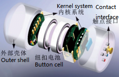
Figure 1 Structure of microchip measuring device
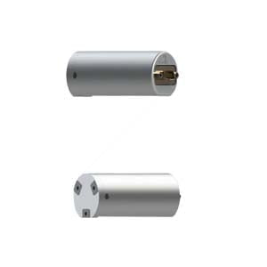
The workflow of the micrometer is shown in Figure 2. The required measurement function is activated prior to use, and then inserted into the drill string at the time of connection, allowing it to move down with the drilling fluid, pass through the drill hole, enter the wellbore annulus, and return to the surface with the annular drilling fluid. Throughout the cycle, the micrometer continuously captures temperature, pressure, triaxial magnetic field strength, and its own triaxial acceleration and triaxial angular rate. The collected data will be transmitted to the upper computer through the enclosure interface for analysis and processing, and then the whole wellbore temperature and pressure field is constructed, and the complex downhole conditions such as overflow and leakage in the wellbore are judged.
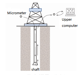
Figure 2 Workflow of microchip measuring device
Research and development of the kernel system
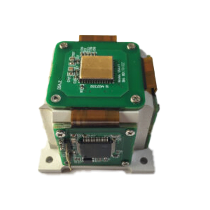
The core system composed of MEMS sensor and integrated circuit board is the core of micrometer. Since the drill hole has a strict limit on the overall size of the measuring instrument, the core system must first control its geometry. However, due to the demand of multi-physical field measurement, the number of sensors carried by the measuring device is large, and each sensor must be equipped with auxiliary circuits, which makes the layout of the entire integrated circuit board become extremely complicated. To this end, the author adopts the design idea of combining the soft and hard circuit boards, that is, the core circuit board consists of 3 circular rigid circuit boards (diameter 10 The rigid circuit board is arranged on the MEMS sensor with different functions and its auxiliary electronic components, and the rigid circuit board is connected through the flexible circuit board, and the final connection becomes a complete set of multi-physical field (temperature, pressure, magnetic, dynamic) collaborative measurement circuit. Due to the bendability of the flexible circuit board, the entire kernel system can be folded and placed into the micrometer housing with strong geometric constraints. The bending shape of the specific core circuit board and its processing are shown in Figure 3.
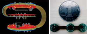
Figure 3 Core circuit system
Also due to the limitation of geometric size, the power supply unit of the micro measuring device uses a micro button battery with a diameter of 9.5mm, so the total capacity of the battery is low, only 53mAh. In this case, the power consumption of each electronic component in the core system needs to be strictly controlled to enable the micrometer to carry out sustained downhole measurements over a long period of time. For this purpose, an external activation interface with ultra-low power consumption is designed, which can quickly wake the micrometer from the ultra-low power shutdown mode to the operating mode. The low power consumption and fast data transmission interface is designed, which can realize the measurement data transmission and control command sending and receiving between the micro measuring device and the host computer. The low-power and high-precision digital temperature sensor, the low-noise three-axis digital magnetic sensor, the high-precision six-axis gyroscope accelerometer sensor and the self-developed Wheatstone bridge pressure measurement module are selected to realize the low-power collaborative measurement of the four parameters of temperature, pressure, magnetic field and dynamics in the wellbore. In addition, the STM32L4 series of low-power microprocessors embedded with large-capacity Flash memory are used to further reduce system power consumption and extend the working time of the micrometer. At present, the main functions of the microprocessor include power management based on low power consumption, system clock and peripheral clock configuration, sensor initialization and parameter configuration, sensor data acquisition and data storage, data transmission between the microcontroller and the host computer. In summary, through the ultra-low power design of the core system, its working current can be maintained at about 3mA, when the micro-button battery with a capacity of 53mAh is selected, the measuring device can work in principle for 17.66h, although the energy consumption in the high temperature environment will generally increase slightly, but the basic requirements of 5~10h working time can be done. The overall core system design block diagram of the micrometer is shown in Figure 4.
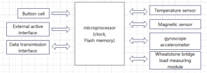
Figure 4 Schematic of core circuit system
External shell development
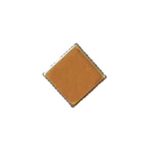
In consideration of the high temperature, high pressure and high corrosion environment, the shell of the micro-measuring instrument was made of high strength polyether ether ketone (PEEK) material. The melting point of the material is 343℃, the tensile strength is 132~148MPa, has the outstanding characteristics of high temperature resistance, corrosion resistance, good mechanical properties, and can better adapt to the complex underground environment. In addition, in order to further improve the pressure resistance of the micro measuring instrument, liquid silicone material polydimethylsiloxane (PDMS) is used to fill the gap between the inside and outside two parts, and the shell is poured to form a protective film, thus forming an organic whole and improving the tightness of the micro measuring instrument. The miniature measuring instrument after packaging is shown in Figure 5, and its maximum diameter and height are strictly controlled to be less than 15 mm; In addition, by adjusting the carbon fiber content of PEEK materials and the gas-bearing porosity of PDMS, the density of the micrometer can be adjusted in the range of 1.1 to 1.8g/cm3.
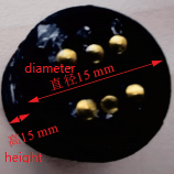
Figure 5 Encapsuled microchip measuring device
Conclusion
As a micro measuring device, only the volume of MEMS gyroscope can meet the standard, and the underground temperature is high, and the tolerance temperature of the gyroscope and equipment is also required. Most MEMS gyroscopes can reach a maximum temperature of 85 ° C, but the ER-MG2-022 developed by Ericco can reach a maximum temperature of 125 ° C, which can better adapt to the underground working environment.
As the first part, this paper mainly describes the overall design of the micro measuring device, the development of the core system, the development of the external shell, and introduces the basic information of the micro measuring device. The second part will focus on the experimental results and calculations.
If you are interested in other MEMS knowledge, you can click on the related products and articles below to learn. If you are interested in the knowledge of MEMS gyroscope micrometer introduced in this article, stay tuned for the release of the second part.
More Technical Questions
1.MEMS gyroscope: A downhole multiphysics measuring device-2
2.Analysis of drive loop noise of MEMS gyroscope
3.What’s the north-seeking principle of MEMS gyroscope?
4.Borehole north finding: Shock vibration compensation for MEMS gyroscope
5.Bias Temperature Compensation Analysis of MEMS Gyroscope
6.How does MEMS gyroscope work in harsh high temperature environment?
Products in Article


.jpg)