Nowadays, MEMS gyroscope is being used more and more widely, and oil drilling is one of them. The borehole north finding system based on MEMS gyro needs to overcome the complex environment, and shock vibration is one of the main factors affecting the measurement accuracy of borehole north finding with MEMS gyroscopes. When shock vibration occurs, MEMS gyro is sensitive not only to the horizontal component of earth rotation, but also to the angular velocity component generated by shock vibration interference. Therefore, in order to improve the precision of north finding while drilling, it is necessary to compensate the error of MEMS gyro under shock vibration. In the following, the influence of vibration on borehole north finding, the application of Mallat algorithm in borehole north finding while drilling system, and the shock vibration error compensation experiment and result analysis of MEMS gyro are discussed.
Effect of vibration on borehole north finding
When the drill bit is drilling, it will not only cause the tilting of the base of the north finder, but also cause high frequency interference due to shock vibration. In practice, the situation is very complicated, MEMS gyroscope will be sensitive to other signals in addition to the Earth's angular rate component, such as drilling the base Angle to produce additional angular speed. The final output of a MEMS gyro consists of a superposition of many signals. In this section, the angle vibration of drilling bit is taken as the main research object, and the error caused by it is analyzed. Bit drilling will make the transverse roller and pitch axis of MEMS gyro do different angular vibration, the specific characteristics are as follows:
β(τ)=βmsinΩτ
γ(τ)=γmcosΩτ
In the formula, βm and γm represent the vibration amplitude of the MEMS attitude meter around the pitch axis and the transverse roller axis, and Ω is the vibration frequency, then the influence angular velocity brought by the drill bit drilling is:
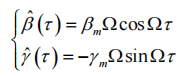
On the basis of two-position north finding, the output after adding only vibration error is:
ω0-ω180=2ΩNcosβcosα+2βmΩcosΩτ
The north seeking angle obtained from the above formula is:
![]()
Expand to get:
![]()
Among them, Δα0 belongs to the north seeking error introduced by the drill bit. From the above formula, it can be seen that when the sensitive axis of the gyroscope approaches north or south, cosα approaches 1 and has the least impact on the error; when it approaches east-west, cosα approaches 0 and has the greatest impact on the error. At present, there are two main ways to reduce borehole vibration errors while drilling: The first is to install shock isolation and shock absorption materials at the drill bit to physically buffer and reduce the impact of shock and vibration on the north finding accuracy of MEMS gyroscope. This method will cause the volume of the whole north finding system to increase and affect the drilling of the drill bit; The second method is to reduce the impact of shock vibration by means of algorithm compensation, such as using an accelerometer that can sense angular velocity and disturbance angular velocity at the same time to compensate the gyroscope output signal, but the accuracy of this method is affected by the accuracy of the additional meter. This paper presents a method based on multi-resolution analysis to solve the effect of drill bit vibration on gyroscope accuracy.
Application of Mallat algorithm in borehole north finding system
During drilling, the accuracy of north finder is affected by various and complex factors. The compensation effect of installing physical anti-vibration materials and using continuous rotation north finding scheme is not very ideal. The effect of north seeking while drilling is the error of multiple interference superposition, which makes it difficult for MEMS gyroscope compensation based on the above method to achieve the ideal precision. It is very practical and significant to use the filtering method to compensate the complex effects while drilling.
Multi-resolution analysis method is a fast transform algorithm using orthogonal wavelet basis, which is widely used in practical engineering applications and more convenient to solve problems, also known as Mallat algorithm. The signal is broken down as follows:
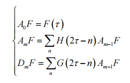
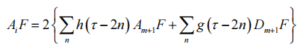
Where F(τ) is the original signal, τ=1.2... N, is the discrete time serial number, m=1.2... M, H and G are the time-domain wavelet decomposition coefficients, and Am is the wavelet coefficient of the low-frequency part of the signal in the m layer. Dm is the high frequency part of the signal at layer m. Mallat algorithm is a progressive algorithm, that is, the initial signal frequency band is divided into high frequency and low frequency parts, and then the low frequency part is used as the high frequency part of each layer below, which is divided by half band. The signal decomposition network structure of Mallat algorithm is shown in Figure 1.
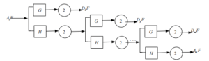
Figure 1 Mallat algorithm decomposes the network structure
Mallat is designed to wavelet transform the filtered signal, remove the noise coefficient, and retain the signal wavelet coefficient, that is, to achieve wavelet filtering. Wavelet threshold method is the easiest method to achieve this purpose, and it is also the most commonly used in practice.
The collected gyroscope output is the fusion data of signal and noise. The noise is dispersed relative to the useful signal in the wavelet domain, and the wavelet coefficient of the signal is greater than that of the noise. By setting a threshold, the wavelet coefficient below the threshold is set to 0, the wavelet coefficient at and above the threshold is retained, and then the signal reconstruction of the processed wavelet coefficient is carried out to recover useful signals, and the filtering of Mallat algorithm can be realized.
The signal reconstruction algorithm is as follows:
Where, h and g are the wavelet reconstruction filter coefficients in the time domain. The signal reconstruction and Figure 1 is the reverse process, as shown in Figure 2.
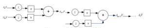
Figure 2 Reconstructed network structure of Mallat algorithm
Experiment and result analysis of shock vibration error compensation for MEMS gyroscope
In order to verify the effectiveness of Mallat algorithm in compensating the shock vibration error of MEMS gyroscopes, a shock vibration experiment was set up. Firstly, the wavelet base suitable for Mallat algorithm is selected. In the borehole north finding while drilling system, the useful signal output of MEMS gyro is the low-frequency part, and borehole north finding should be completed in a short time, resulting in limited data points collected. Therefore, the wavelet base with higher vanishing moment and better linear phase should be selected. To ensure that the energy after wavelet transformation is concentrated in the low frequency part and reduce the edge distortion after signal reconstruction.
Symlets wavelets are approximately symmetric wavelets, usually expressed as symN (N=2,3,... ,8). It is a kind of wavelet with orthogonality and compact support and can be transformed continuously and discretely. It conforms to the characteristics of wavelet required in this paper, and is suitable for the signal filtering of MEMS gyros while drilling. It has a support length of 2N-1 and can provide a high vanishing moment. Since the low-frequency signal is the main signal collected, theoretically speaking, the larger the decomposition scale, the better the filtering effect, but the borehole north finding time is limited, too few sampling points may cause filtering distortion. Therefore, sym8 wavelet is selected with a filter length of 2N and a value of 16.
Considering the calculation amount of sym8 wavelet, rounding error, delay and other factors, the decomposition scale of sym8 wavelet is finally chosen as 4. The impact vibration test platform is shown in Figure 3.
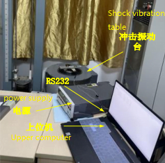
Figure 3 Schematic diagram of simulation disturbance experiment platform
The specific experimental steps are as follows: the MEMS gyroscope based attitude meter is fixed on the turntable and powered up to preheat to ensure the normal data. The sampling frequency is set to 100Hz to simulate the underground scene. The shock vibration table is set to 1000g and the vibration frequency is 20Hz. First, the data output was collected in the static state, and the impact and vibration interference of MEMS attitude instrument was simulated by the console during drilling while drilling. The Mallat algorithm was used to decompose and then reconstruct the data. The comparison of X axis output before and after filtering was shown in Figure 4.
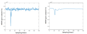
(a) Output before shock vibration compensation (b) Output after shock vibration compensation
Figure 4 Comparison of Mallat algorithm before and after filtering compensation
As can be seen from the comparison diagram of filtering results reconstructed after decomposition by Mallat algorithm, this algorithm has a good filtering effect on vibration and noise influence of MEMS gyro north finding system while drilling, but the interference caused by impact still exists obviously, which will greatly affect the north finding accuracy. As can be seen from Figure 4, the error effect caused by the impact is only in the time period in which the impact exists, and other time periods are not affected by the impact. Based on this characteristic, a segmented processing method based on output time is proposed. Specific operations are as follows:
1. Collect the output of MEMS gyroscopesunder shock vibration. ωa, a=1.2... X, divide X data into Y groups, and the number of data in each group is c=X/Y;
2. Calculate the mean and mean square error snof each group, where the value of n is the number of data collected. Each group is weighted, because the mean square error is inversely proportional to the weighting coefficient, then the weighting coefficient of each segment is 1/sn;
3. Normalized the weight coefficient and weighted the sum of each set of data to get the final output as follows:
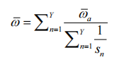
When there is no impact, the mean output of the MEMS gyro is 1.1711×10⁻³°/s; when there is impact interference, the mean data is 1.1026×10⁻³°/s, and the difference is 0.0685×10⁻³°/s. The data in MEMS gyros 140s were divided into different groups and weighted. The output is shown in Table 1.
| Segment number Y | Each time/s | Weighted output /×10-3°/s | Interpolation difference before and after processing /×10-3°/s |
| 5 | 28 | 1.1688 | 0.0606 |
| 7 | 20 | 1.1679 | 0.0622 |
| 10 | 14 | 1.1684 | 0.0637 |
| 14 | 10 | 1.1683 | 0.0629 |
Table 1 Results of piecewise weighted processing of impulse interference data
As can be seen from Table 1, although the number of segments and the time of segments are different, the difference results after weighted output and processing are not much different, and each group of data is close to the data output without impact, indicating that the method of time-weighted segmentation can effectively suppress the impact of impact on the output of MEMS gyro. It can be seen that Mallat algorithm combined with time-weighted method can effectively suppress the error influence caused by shock vibration when MEMS gyroscope is used in borehole MWD system, thus improving the north finding accuracy.
Conclusion
Shock vibration will affect the borehole north finding system based on MEMS gyro, so how to compensate is very important. In this paper, the influence of vibration on borehole north finding is introduced, and a new method, Mallat algorithm, is proposed, and its application in borehole north finding system while drilling is analyzed. Experiments show that this new method can effectively suppress the impact of shock vibration.
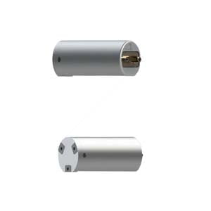
Due to the harsh working environment, MEMS gyroscopes should have such conditions as shock and vibration resistance, high temperature resistance and strong adaptability for borehole drilling while drilling. ER-MG2-022, as a MEMS gyroscope specially developed for borehole gyro tools, has excellent shock and vibration resistance, and the working temperature can reach 125℃. It can help gyro tools better complete borehole work.
Through this article, I hope you have some understanding of MEMS knowledge. If you want to learn more, please click on the related articles and products below to learn.
More Technical Questions
1.System error and calibration of MEMS gyroscope
2.Sensitive structure analysis of MEMS gyroscope
3.Comparative analysis of typical high performance MEMS gyroscopes
4.The impact of turntable error on MEMS gyroscope calibration
5.The analysis of damping in MEMS gyroscope
6.How does MEMS gyroscope work in harsh high temperature environment?
Products in Article


.jpg)