Do you know any calibration methods for MEMS gyroscopes?
Introduction
MEMS gyroscope, as one of the typical MEMS sensors, has the advantages of small size, low cost, low power consumption and high reliability, and is a research hotspot in the field of inertial navigation. Due to mechanical errors in mechanical structure or manufacturing process, almost all MEMS gyroscopes have measurement errors caused by acceleration, which are called acceleration-sensitive drift errors.
In the past, because the measurement accuracy of MEMS gyro is low, in the modeling study, most of them only considered the influence of bias error, non-orthogonal error and scale factor error on the measurement precision of gyroscope, without considering the acceleration sensitivity drift error. In recent years, with the breakthrough of MEMS gyroscope in electronic control, microstructure, process platform and integrated application technology, its measurement accuracy has been significantly improved. The establishment of the output model of MEMS gyroscope considering acceleration-sensitive drift error is an important premise to improve its measurement accuracy and make it applied in the field of higher precision navigation.
How to measure the acceleration of a gyroscope?
In general, the gyroscope and accelerometer from an IMU(inertial measurement unit), which measures angular rate and acceleration. The angular rate measuring unit consists of three gyroscope, whose output angular rate contains non-orthogonal error and acceleration-sensitive drift error related to input acceleration. The calibration method of MEMS gyroscope non-orthogonal error and acceleration-sensitive drift error is suitable for MEMS gyroscope whose bias stability is lower than 1° / h. In the calibration process, the acceleration data is provided by the accelerometer in the inertial measurement unit, and the axial direction of the accelerometers coincides with that of the gyroscopes. Therefore, the output data of the accelerometer after error correction is the acceleration value of the corresponding axis of the gyroscope.
Calibration steps for high precision MEMS gyro
The traditional gyroscope multi-position turntable calibration only considers the influence of bias and non-orthogonal error. In order to calibrate and correct the acceleration-sensitive drift error, we design a calibration scheme for the 16-position turntable. The calibration steps are as follows:
1) Rotate the inner and outer frames of the two-axis turntable so that the positions of the turntable are successively shown in the figure, and collect the data of the three-axis MEMS gyroscope and accelerometer of the 16 positions of the turntable respectively under static conditions;
2) The collected gyroscope and accelerometer data are grouped and then smoothed;
3) Calibrate and compensate the bias error of MEMS gyroscope;
4) Calibrate the acceleration-sensitive drift error and non-orthogonal error of the gyroscope at the same time.
Gyroscopes with bias stability lower than 1° / h can accurately be sensitive to the earth rotation rate after reducing the influence of noise. Therefore, in this scheme, the components of the earth rotation rate on three axes will be selected as the excitation angular rate of the gyroscope.
When adjusting the position of the turntable, there is no need to collect gyroscope data, so the rotation mode of the turntable will not affect the calibration results. It is only necessary to adjust the inner and outer frames of the biaxial turntable to make the position of the turntable in turn 16 positions as shown in the figure.
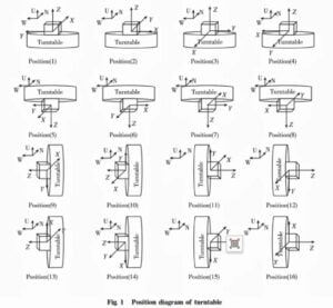
Because the acceleration-sensitive drift coefficient of gyroscope needs to be calibrated, it is necessary to ensure that each axial gyroscope is subject to at least two different specific force excitations in addition to more than two angular rate excitations. In this article, -g, 0 and g are selected as the excitation acceleration of the gyroscope, and the position states of 16 turntables shown in the figure are designed while considering the sufficiency of excitation and calibration efficiency.
More Technical Questions
1.Feasibility Analysis of MEMS Gyro North Seeking
2.How do MEMS gyroscopes work?
3.MEMS gyroscope VS FOG: What’s the difference between them?
4.How to Weld and Install High Performance MEMS Gyro
5.How to Configure the Register of Ericco MEMS Gyro
6.What is the Hardware Interface of Ericco MEMS Gyro
Products in Article