1.Application products
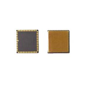
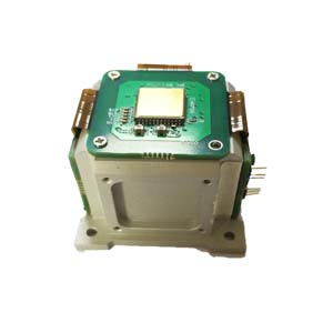
North seeking MEMS Gyro ER-MG2-100
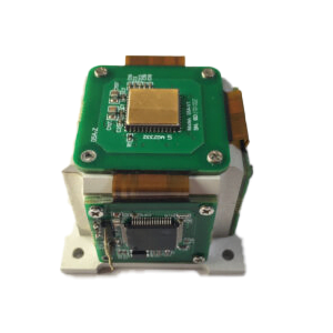
Navigation grade MEMS Gyro ER-MG2-300/400
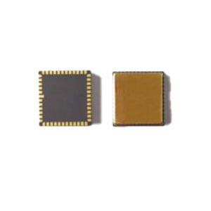
Tactic grade MEMS Gyro ER-MG-067
2.Welding suggestions
Please refer to IPC/JEDEC J-STD-020D.1. The reflow curve depends not only on the sensor but also on the PCB board. To improve welding reliability, it is recommended to use plates with a coefficient of thermal expansion (CTE) close to that of the gyro package (6.8 PPM /°C). The following material is taken from IPC/JEDEC J-STD-020D.1
 of MEMS gyro")
FIG. 12 Reflux Curve (JEDEC)
| Features | Sn, Pb welding | Lead-free soldering |
| Average rate of increase (TSmax to TP) | The biggest 3°C/second | The biggest 3°C/second |
| Preheating
Minimum temperature value (Tsmin) Maximum temperature (Tsmax) Time (TS) |
100°C
150°C 60-120 s |
100°C
200°C 60-180 s |
| Time to maintain
Temperature (Tl) Time (Tl) |
183°C, 60-150 s | 217°C, 60-150 s |
| Peak temperature (To) | 240°C(+/-5°C) | 260°C(+/-5°C) |
| Actual peak temperature (TP) hold time at 5°C | 10-30 s | 10-40 s |
| scale of decrease | Maximum 6 ° C/second | Maximum 6 ° C/second |
| Time from 25°C to peak temperature | Maximum 6 minutes | Maximum 8 minutes |
3.ESD Prevention suggestions
 |
ESD(electrostatic discharge) sensitive device. Live devices and circuit boards can be electrically charged without being noticed. Although this product has a proprietary protection circuit, the device may be damaged in the event of high energy ESD. Therefore, appropriate ESD preventive measures should be taken to avoid device performance degradation or function loss. |
3.1 Environmental control: all electrostatic sensitive device manufacturing, production, operation, turnover, storage area belongs to the electrostatic protection area, it is recommended to control the temperature and humidity, temperature: 20~30℃, relative humidity (RH) : 40~75%.
3.2 Antistatic identifier: There should be an antistatic identifier in the antistatic working area to warn anyone who touches the electrostatic sensitive device that electrostatic protection must be carried out when operating the device.
3.3 Anti-static floor: anti-static working area should be laid anti-static floor, regular monitoring of surface resistance and grounding resistance.
3.4 Grounding control: the anti-static working area of a variety of equipment, a conductive part of the instrument through the conductor and grounding body for electrical connection, regular check to ensure that the grounding is good.
3.5 Anti-static workbench: the surface of the anti-static workbench should be composed of electrostatic dissipation materials or laid anti-static radio pad and effective grounding, all contact with it with electrostatic devices will be through its surface to the ground of the distribution of resistance slowly and safely discharge.
3.6 Personnel: all personnel entering the anti-static area must wear anti-static work clothes, anti-static work shoes or anti-static shoe cover, contact with electrostatic sensitive devices should also wear anti-static wrist. Regular ESD protection training and promotion, enhance
All personnel are aware of ESD prevention.
3.7 anti-static packaging: electrostatic sensitive devices, components, products in the production, storage and transportation of the materials used must be anti-static materials.
4.Installation reference
High-performance MEMS gyros are high-precision test equipment. In order to achieve the best design results, it is recommended to consider the following aspects when installing devices on the PCB board.
4.1 In order to evaluate and optimize the placement of sensors on the PCB, it is recommended to consider the following aspects and use additional tools during the design phase:
On the thermal side;
On mechanical stress: bending measurement and/or finite element simulation;
On impact robustness: After welding the PCB applied to the target in the recommended manner, a drop test is performed.
4.2 It is recommended to maintain a reasonable distance between the sensor installation position on the PCB and the key points described below (the exact value of "reasonable distance" depends on many customer specific variables and must therefore be determined by specific circumstances) :
It is generally recommended to minimize PCB thickness (recommended :1.6 to 2.0 mm) because thin PCB boards have lower inherent stresses;
It is not recommended to place the sensor directly under or near the button because of mechanical stress.
It is not recommended to place the sensor near extremely hot spots (such as controllers or graphics chips) as this will heat up the PCB and cause the temperature of the sensor to rise.
More Technical Questions
1.The Calibration Method of High Precision MEMS Gyro
2.What is the Hardware Interface of Ericco MEMS Gyro
3.Feasibility Analysis of MEMS Gyro North Seeking
4.How to Distinguish MEMS Accelerometer and MEMS Gyroscope Correctly?
5.ER-MG2-100 (0.02°/h) High Precision MEMS Gyroscope
6.Analysis of the main performance parameters of MEMS gyroscope
Products in Article