


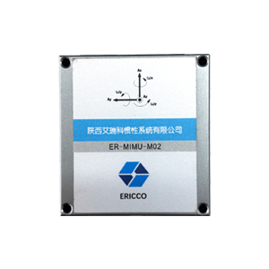
ER-MIMU-M02 High Performance MEMS IMU
Introduction
IMU is an abbreviation for Inertial Measurement Unit, which mainly consists of a three-axis gyroscope and a three-axis accelerometer. It can measure the angular velocity and linear acceleration of an object in real time, autonomously sensing motion without relying on satellites or external signals, and calculating attitude, tilt angle, heading, and trajectory through integrated algorithms.
Features
Three-axis digital gyroscope:
Dynamic measurement range: ±450º/s;
Bias instability: 2 º/h (Allan variance);
Angular random walk: 0.15º/√h.
Three-axis digital accelerometer:
Dynamic measurement range: 16g;
Bias instability: 24μg (Allan variance);
High reliability: mean time between failures > 20000h;
Ensure accuracy over the full temperature range (-40°C~80°C): Built-in high-performance temperature calibration and compensation algorithm;
Communication interface: 1 SPI, slave mode.
Application
Space-based fields: unmanned aerial vehicles, aerial photography, agricultural plant protection, photoelectric detection stability;
Land-based fields: vehicle navigation, vehicle satellite communications, forest and land monitoring, high-speed railway track inspection;
Sea-based fields: hydrological Measurement, waterway detection, shipboard positioning communication, unmanned surface vehicle.
Specifications
| Parameter | Test condition | Min value | Typical value |
Max value |
Unit |
| Gyroscope | |||||
| Measuring range | ±450 | º/s | |||
| Bias instability | Allan variance | 2 | º/h | ||
| Bias stability | 8 | º/h | |||
| Random Walk | 0.15 | º/√h | |||
| Bias Repeatability | 1 σ | 6 | º/h | ||
| Accelerometer | |||||
| Measuring range | ±16 | g | |||
| Bias instability | Allan variance | 24 | μg | ||
| Bias stability | 200 | μg | |||
| Bias Repeatability | 1 σ | 200 | μg | ||
| Magnetometer | |||||
| Dynamic measurement range | ±2.5 | Gauss | |||
| Resolution | 120 | uGauss | |||
| Noise Density | 50 | uGauss | |||
| Bandwidth | 200 | Hz | |||
| Barometer | |||||
| Pressure range | 450 | 1100 | mbar | ||
| Overall error | 6 | ||||
| Resolution | 0.1 | mbar | |||
| Absolute measurement accuracy | 1.5 | mbar | |||
| Long-term stability | ±1 | mbar/yr | |||
| Communication Interface | |||||
| 1 way SPI | Baud rate | 15 | MHz | ||
| Electrical specification | |||||
| Voltage | 3 | 3.3 | 3.6 | V | |
| Power dissipation | 1.5 | W | |||
| Ripple wave | P-P | 100 | mV | ||
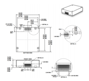
| Structural characteristics | |||||
| Dimension | 47×44×14mm | ||||
| Weight | 50 | g | |||
| Operating environment | |||||
| Operating temperature | -40 | 80 | ℃ | ||
| Storage temperature | -45 | 85 | ℃ | ||
| Vibration | 3g, 10~2000Hz | ||||
| Impact | 30g, 11ms | ||||
| Mean time between failures | 20000 | h | |||
| Reliability | |||||
| Continuous working hours | 120 | h | |||
Dimension
")
Coordinate system definition
The coordinate systems for the 3 gyroscopes (x g, y g, z g) and 3 accelerometers (x a, y a, z a) are defined as shown in the figure below, with the arrows in a positive direction.
Read and write data
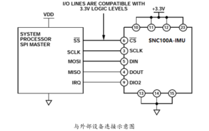
ER-MIMU-M02 is an autonomous sensor system that automatically activates when an active power supply is present. Once the initialization process is complete, it begins sampling, processing, and loading the calibrated sensor data into the output registers, which can be accessed via the SPI port. The SPI port is usually connected to a compatible port of the embedded processor, and the connection diagram is shown in the figure. Four SPI signals support synchronous serial data transmission. In the factory default configuration, the DIO2 pin provides a data-ready signal; When new data is available in the output data registers, the pin goes high.
1 General Purpose Host Processor SPI Settings
| Processor settings | introduce |
| Host mode | ER-MIMU-M02 used as a slave |
| SCLK ≤ 15 MHz | Maximum serial clock rate |
| SPI mode 3 | CPOL = 1 (polarity), CPHA = 1 (phase) |
| MSB Priority mode | Positional order |
| 16-bit mode | Shift register/data length |
2 SPI Communication
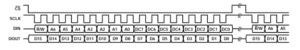
If the previous command is a read request, the SPI port supports full-duplex communication, and the external processor can write DIN at the same time as reading DOUT, as shown in the following figure.
2.1 SPI read and write timing
Read sensor data
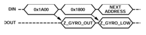
The ER-MIMU-M02 automatically starts and activates page 0 for data register access. After accessing any other page, the 0x00 should be written to the PAGE_ID register (DIN = 0x8000) to activate page 0 in preparation for subsequent data access. A single register read operation requires two 16-bit SPI cycles. In the first cycle, the bit allocation function in Figure 1 is used to request a read of the contents of a register; In the second cycle, the register contents are output via DOUT. The first digit of the DIN command is 0, followed by the high or low address of the register. The last 8 bits are extraneous, but the SPI requires the full 16 SCLKs to receive requests. The following diagram shows two consecutive register reads, first DIN = 0x1A00, requesting the contents of the Z_GYRO_OUT register, and then DIN = 0x1800, requesting the contents of the Z_GYRO_LOW
2.2 Example of an SPI read operation
User Register Memory Mapping
| R/W | PAGE_ID | address | default | Register description |
| R/W | 0x00 | 0x00 | 0x00 | Page identifier |
| R | 0x00 | 0x0E | N/A | temperature |
| R | 0x00 | 0x10 | N/A | x axis gyroscope output, low word |
| R | 0x00 | 0x12 | N/A | x axis gyroscope output,high word |
| R | 0x00 | 0x14 | N/A | y axis gyroscope output, low word |
| R | 0x00 | 0x16 | N/A | y axis gyroscope output,high word |
| R | 0x00 | 0x18 | N/A | z axis gyroscope output, low word |
| R | 0x00 | 0x1A | N/A | z axis gyroscope output,high word |
| R | 0x00 | 0x1C | N/A | x axis accelerometer output, low word |
| R | 0x00 | 0x1E | N/A | x axis accelerometer output,high word |
| R | 0x00 | 0x20 | N/A | y axis accelerometer output, low word |
| R | 0x00 | 0x22 | N/A | y axis accelerometer output,high word |
| R | 0x00 | 0x24 | N/A | z axis accelerometer output, low word |
| R | 0x00 | 0x26 | N/A | z axis accelerometer output,high word |
| R | 0x00 | 0x28 | N/A | x axis Magnetic output,high word |
| R | 0x00 | 0x2A | N/A | y axis Magnetic output,high word |
| R | 0x00 | 0x2C | N/A | z axis Magnetic output,high word |
| R | 0x00 | 0x2E | N/A | Barometric pressure output,low word |
| R | 0x00 | 0x30 | N/A | Barometric pressure output,high word |
2.3 Transform formulas
Current temperature =25+ TEMP_OUT* 0.00565
| X axis gyroscope for example | X_GYRO_OUT | X_GYRO_LOW |
| 1LSB=0.02°/S | The weight of the MSB is 0.01°/s, and the weight of the successors is half that of the previous one | |
| 0.02*X_GYRO_OUT | 0.01*MSB+0.005*....... |
YZ gyroscopes are calculated in a similar way to X-axis gyroscopes。
| X axis accelerometer for example | X_ACCL_OUT | X_ACCL_LOW |
| 1LSB=0.8mg | The weight of the MSB is 0.4mg, and the weight of the successors is half that of the previous one | |
| 0.8*X_ACCL_OUT | 0.4*MSB+0.2*....... |
YZ accelerometers are calculated in a similar way to X-axis accelerometers。
| X x axis Magnetic | X_MAGN_OUT |
| 1LSB=0.1mGauss | |
| 0.1*X_MAGN_OUT |
YZ axis magnetometers are calculated in a similar way to X-axis magnetometers。
| Example of barometric pressure calculation | BAROM_OUT | BAROM_LOW |
| 1LSB=40ubar | The MSB is weighted at 20ubar, and the successors are weighted half the weight of the previous one | |
| 40*BAROM_OUT | 20*MSB+10*....... |
Note: For gyroscope, accelerometer, magnetic fraction high 16bit, and low 16bit, the final result of addition is calculated separately
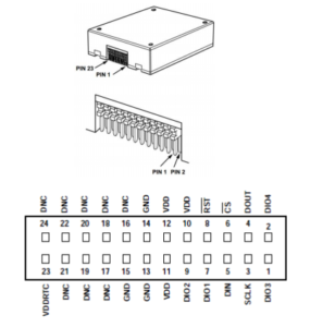
Electrical interfaces
| Pin serial number | name | type | description |
| 10,11,12 | VDD | power supply | |
| 13,14,15 | GND | Power Ground | |
| 7 | DIO1 | I/O | Generic I/O, configurable |
| 9 | DIO2 | I/O | |
| 1 | DIO3 | I/O | |
| 2 | DIO4 | I/O | |
| 3 | SPI-CLK | input | The SPI defaults to slave mode |
| 4 | SPI-MISO | output | |
| 5 | SPI-MOSI | input | |
| 6 | SPI-CS | input | |
| 8 | RST | input | reposition |
| 16~24 | NC | spare | Manufacturer reserved |
Exterior structure
The product is mounted through 4XΦ2.4 through holes, and 4XM2 screws (plus elastic washers and flat washers) are used for mounting. When the connector is installed, the plug should be connected to the receptacle. The product mating connector is Samtec CLM-112-02-L-D
Application Techniques
1.Do you know the core components that give precise control to automated equipment
2.High-performance IMU: A New Benchmark for Precise Measurement and Control
3.Industrial Versatile Tool: High Cost-Performance IMU Meets Diverse Needs
4.Flight safety secrets: The core role of high-precision IMUs in aviation
5.Revolutionizing drone navigation: How to redefine high performance and low cost
6.From flight control to fault diagnosis, how does IMU dominate drones?
More Products
 North-Seeking MEMS IMU
 High Accuracy North-Seeking MEMS IMU
 North Seeking Mems Imu For Gyro Tools
 North-seeking MEMS IMU
 Economical MEMS Gyroscope