In the servo circuit of Q-Flex accelerometer, the essential purpose of detecting the differential capacitance sensor in the head is to realize the measurement of the deflection angle of the pendulum, so the detection accuracy of the differential capacitance plays a decisive role in the accelerometer's performance indexes such as resolving power, stability and linearity. At present, the more mature differential capacitance detection methods mainly include bridge capacitance detection circuits and switching capacitance detection circuits.This article introduces research on the differential capacitance detection technology for Q-Flex accelerometer.
Bridge capacitance detection circuits are mainly realized in the form of triangular wave current bridge modulated detection circuit, dual-carrier bridge modulated detection circuit and single-carrier bridge modulated detection circuit.
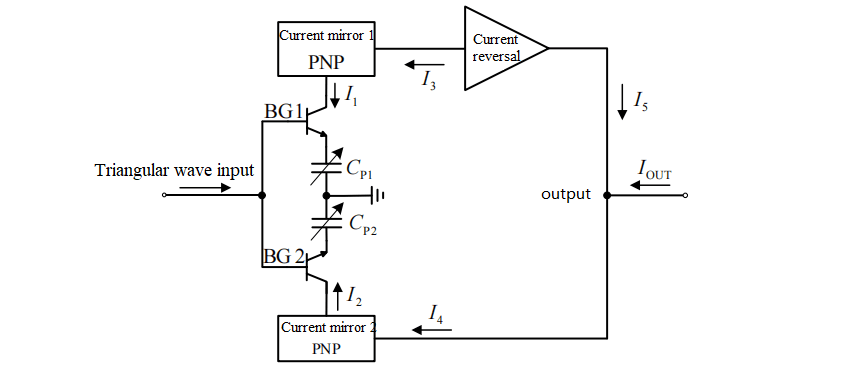
Fig.1 Schematic diagram of differential capacitance detection method in servo circuit
Differential capacitance-voltage converter chip LZF15 utilizes a triangular wave current bridge modulated detection circuit to realize differential capacitance detection, and its basic principle is shown in Fig. 1, which adopts transistors BG1 and BG2 as analog switches, and uses a triangular wave to charge/discharge the differential capacitors CP1 and CP2, thus forming AC currents I1 and I2 that are proportional to CP1 and CP2, respectively, and current mirrors 1 and 2 can ensure that currents I1 and I2 are proportional to CP1-CP2. The current mirrors 1 and 2 ensure that the currents I1=I3 and I2=I4. The subtraction operation between the currents I3 and I4 is realized by the current inverter, and the output current I5 after the subtraction operation is proportional to the CP2-CP1, i.e., it realizes the differential capacitor-current conversion. Then, LZF15 chip through the integral circuit and preamplifier circuit will be the above current signal into the corresponding voltage signal. The detection principle of this method is relatively simple, but only about 0.01pF differential capacitance detection resolution can be realized, which limits the measurement resolution of Q-Flex accelerometers.
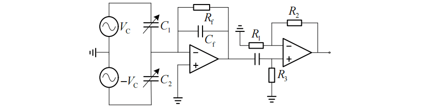
Fig.2 Double carrier bridge modulated differential capacitance detection circuit
The basic principle of the dual-carrier bridge modulated differential capacitance detection circuit is shown in Fig.2. The method uses two high-frequency carrier signals with the same frequency and opposite phase to charge and discharge the two measured capacitors respectively, and a single detector is used to realize the front charge amplification.
This capacitance detection method has a simple circuit structure and does not require a symmetrical circuit structure, which avoids the measurement error caused by the inconsistency of circuit components. However, this method requires that the two carrier signals have exactly equal peak voltages, equal frequencies and opposite phases, which makes it extremely difficult to realize this dual-carrier signal and the results are usually unsatisfactory.
The basic principle of the single-carrier bridge modulated differential capacitance detection circuit is shown in Fig. 3. This method uses two completely symmetrical detectors and a differential amplifier circuit to realize differential capacitance detection, the circuit structure is relatively complex, requiring a high degree of consistency between the two detectors, but only a single carrier is required, which is more realizable than a dual-carrier circuit.
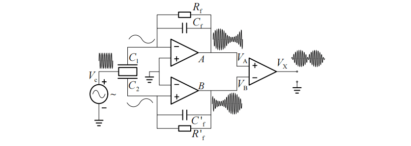
Fig.3 Single carrier bridge modulated differential capacitance detection circuit
The switched capacitance detection circuit uses electronic switches to control the charging and discharging process of the differential capacitance, and converts the differential capacitance change information into an analog voltage or directly into a digital signal output. Figure 4 a) shows a Single-Slope Capacitance-to-Digital Converter (SSCDC) that directly converts differential capacitance change information into a digital signal. b)
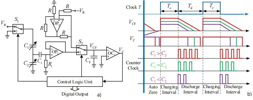
Fig.4 Switch type differential capacitance detection circuit and its sequence diagram
The SSCDC consists of a differential capacitance sensor, an AC-coupled buffer stage (OP1), electronic switches, a comparator ( The SSCDC consists of an AC-coupled buffer stage (OP1), an electronic switch, a comparator (OC1), and a control logic unit (CLU).The charge/discharge timing of the SSCDC, the capacitance waveforms, the comparator waveforms, and the outputs of the counters when the differential capacitance is in different states are shown in Figure 4 b). The switching detection circuit has higher requirements for the charging and discharging timing, and the electronic switch is not suitable for high-precision differential capacitance detection because it is easy to introduce more noise and interference to the analog circuit during the disconnection and closure process.
The output signals of the aforementioned differential capacitance detection methods are all proportional to the differential capacitance C1-C2, but there is a nonlinear sensing relationship with the pendulum deflection angle, which has a principle defect.
Conclusion
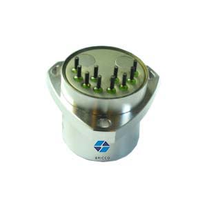
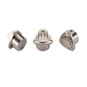
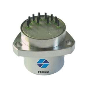
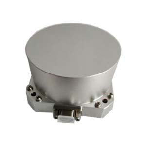
Ericco offers high-precision q-flex accelerometers, such as ER-QA-01A3, with a bias stability of 10 μg, a scale factor repeatability of 10 ppm, and a weight of 80 g. They can be widely used in aircraft carrier microgravity measurement systems, inertial navigation system and static angle measurement system.
More Technical Questions
1. Dynamic Attitude Measurement of Directional Drilling Tools Based on Q-Flex Accelerometer
2. Temperature Compensation Method for Q-Flex Accelerometers
3. Driving Automotive Evolution: MEMS Accelerometers
4. Factors Affecting the Stability of Q-Flex Accelerometers
5. Structure Design of High Precision Quartz Flexible Accelerometer
6. Methods to Maintain the Long-Term Performance of Quartz Flexure Accelerometers
Products In Article