

With the continuous improvement of MEMS gyroscope manufacturing technology, the accuracy of MEMS gyro is gradually improved. The north finding result based on MEMS gyro is directly obtained by the north finding scheme, and the design and implementation of the north finding scheme of MEMS gyro will directly affect the north finding precision. This paper will introduce the segmented north-seeking orientation technology based on MEMS gyro. The following will explain the principle of rotary modulation technology and the new scheme of segmented north-seeking orientation of MEMS gyro.
Principle of rotary modulation technology
Rotational modulation technology was first introduced in ship inertial navigation system in 1980, and gradually applied to signal analysis in the field of north finding in recent years. The role of RMT in the frequency domain is shown in Figure 1. It can be seen that the effective signal is initially immersed in the low-frequency drift of the MEMS gyroscope, but the use of RMT can make the spectrum of the effective signal far away from the low-frequency drift, so as to facilitate signal detection. The signal is modulated to the rotating frequency point using physical rotation, and then the signal is separated from the low-frequency noise, thereby improving the signal-to-noise ratio. When using RMT for north finding measurement, the modulation output of the gyro is an AM wave with a fixed frequency. By analyzing the amplitude modulation signal, the amplitude and phase of the specific frequency signal are obtained, and the phase is the Angle between the gyro measurement axis and the true north direction, that is, the north-seeking value.
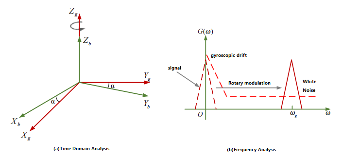
Figure 1 Principle of rotational modulation
The principle of RMT can be qualitatively analyzed from time domain and frequency domain, as shown in Figure 1. Figure 1(a) is the time domain analysis, and for the sake of simplifying the analysis, it is assumed that the b system coincides with the n system. As the g system rotates around the z axis, the effective component of the Earth's rotation rate is projected into the g system, forming a sine or cosine signal. The effective signal measured by MEMS gyro is the modulated signal that can be detected after removing gyro drift or other noise effects. Figure 1(b) illustrates the role of RMT in the frequency domain; It can be seen that the effective signal was originally immersed in the low-frequency drift of MEMS gyro, but RMT can make the spectrum of the effective signal far away from the low-frequency drift, so as to facilitate signal detection. Continuous rotation of the turntable reduces zero bias and scale factor errors.
1/f flicker noise and low frequency drift are the two main errors of low-cost inertial devices. To find north, one must measure the rotation rate of the Earth, which is a small frequency domain DC constant. The signal is submerged in high-amplitude noise, and it is difficult to extract the signal directly from the noise using the general signal processing methods shown in Figure 1. Rotational modulation uses physical rotation to modulate the signal to the rotational frequency point, and then separates the signal from the low-frequency noise, improving the signal-to-noise ratio. Other methods used to obtain the original signal are bandpass filters or demodulation.
When the sensitive axis of MEMS gyroscope rotates with the turntable mechanism, its output characteristics show a periodic amplitude modulation curve, so its output is affected by the speed and performance of the turntable. Meanwhile, the random drift characteristics of MEMS gyro itself, constant drift and various low-frequency disturbances in the external environment will also interfere with the output data. The gyro output in continuous rotation dynamic north seeking is more complicated than the static output. When the MEMS gyro remains horizontal, the dynamic output model of the MEMS gyro over time is as follows after rotating and modulating at a constant angular rate by the turntable:
ω(t)=ωNcos(Ωt+α)+ε0+εt
In the formula, Ω=2Πƒ0, is the rotation angular rate of the turntable, the unit is rad/s; ƒ0 is the rotation frequency of the rotary table, in Hz.
MEMS gyro outputs at a certain sampling frequency, and each sampling time corresponds to a sampling point. The output of MEMS gyro is expressed as the output related to its sampling frequency and modulation frequency:
ω(i/ƒs)=ωNcos(2Π(ƒ0/ƒs)i+α)+ε0+εt
In the formula, ƒs is the sampling frequency of MEMS gyroscope
i -- sampling number, i=1,2,... N,N is the total number of sampling points
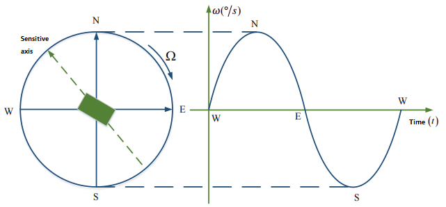
Figure 2 Relation between the position of gyroscopic sensitive axis and the output amplitude
As can be seen in Figure 2, the output is a cosine wave with a fixed amplitude and frequency. The northbound component of the Earth's rotation rate can be made into a cosine signal by continuous self-modulation. The peak of the curve corresponds to the position of the MEMS gyro sensitive axis and the true north direction, and the zero crossing of the curve corresponds to the due east and due west directions respectively.
A new MEMS gyroscope segmented north-finding orientation scheme
1. Horizontal axis fusion northfinding output
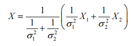
As a micromechanical inertial measurement unit is adopted in this paper, which has three gyroscopes and the two pairs are orthogonal to each other, two groups of MEMS gyroscopes are settled for north seeking according to the characteristics of using horizontal axis for data acquisition in the process of north seeking. Since the horizontal axis direction difference is 90° in the experiment, the two groups of north seeking results can be merged to obtain a new north seeking result. The north finding accuracy of MEMS gyro is increased. This method adopts the weighted average method, and the principle is as follows: Assume that the two measurement signals obey the normal distribution N(μi,σi2),i=1,2, where μi is the mean value of signal measurement, indicating the mean square error of signal measurement noise, and its size reflects the size of signal measurement noise drift. The weighted average fusion of the two signals is calculated as follows:
The noise mean square error of the fused signal X is as follows:
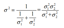
From the above formula, σ<σ1 and σ<σ2 can be obtained, which proves that the precision result of the fused signal is better than that measured by a single axis.
2. Segmented new scheme implementation
The flow chart of the new MEMS gyroscope segmented north finding scheme 3 is as follows:
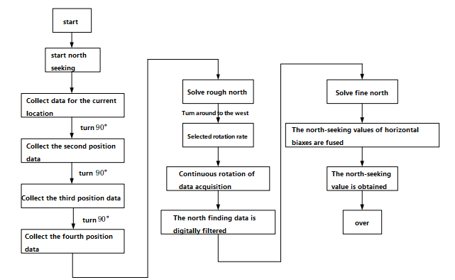
Figure 3 Flowchart of the new segmented north finding scheme
The above flow chart is described as follows: After the device is powered on, the upper computer sends the command to the MEMS gyro to start north finding. After receiving the command, the MEMS gyro collects the MEMS gyro data of the current position, and then sends the Angle command to the turntable mechanism to make the MEMS gyro rotate 90° clockwise to reach the second position. At the same time, the MEMS gyro data of the same length as the previous position is collected at this position, and so on until the data of the fourth position is collected. After collecting the MEMS gyro angular rate data of these four positions, the coarse north seeking value is calculated according to the four-position north seeking method. According to the coarse north seeking value, the rotation mechanism is turned to the west orientation, the west orientation is the initial position, and continuous rotation dynamic north seeking is carried out after the rotation rate is set. At the same time, the MEMS gyro data is collected, filtered by digital filter, and the precise north finding values of the horizontal two axes are calculated by the solution algorithm, and the two results are fused to obtain the final north finding results.
Conclusion
This paper introduces the segmented north seeking orientation of MEMS gyro. With the development of MEMS gyro more and more rapidly, it can be self-seeking north and has a variety of single axis, two axis and three axis choices. The dual-axis MEMS Nord-seeking gyro ER-2MG-01 has the function of attitude measurement, while the three-axis MEMS Nord-seeking gyro ER-3MG-01 can be directly developed on the basis of the system, and different algorithms can be added to obtain different nord-seeking/inertial systems. The ER-MG2-50/100 is a navigation-grade MEMS nord-seeking gyro that can self-find north, and its accuracy level can meet the needs of multiple applications.
I hope that through this article you can understand the MEMS gyroscope, for single-axis, two-axis and three-axis MEMS gyroscope north finding scheme, which scheme will you choose?
More Technical Questions
1.Integrated method of three-axis MEMS gyroscope
2.Development history of MEMS gyroscope
3.MEMS gyroscope processing technology
4.Evolution of resonant structure of high precision MEMS gyroscope
5.MEMS Gyroscope: Sensitive Structure | Detection Circuit | Integrated Package
6.Signal Denoising Principle And Evaluation Index of MEMS Gyroscope
Products in Article
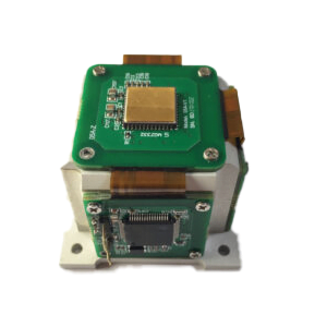 3-Axis North-Seeking MEMS Gyro

High Accuracy Single-Axis MEMS Gyro
 2-Axis North-Seeking MEMS Gyro
High Precision Stable-Control MEMS IMU