MEMS gyroscope machining technology is a kind of micro machining technology for structural scale from nanometer to millimeter. MEMS processing technology in a broad sense involves most of the modern processing technology, according to the different technical approaches, can be roughly divided into three kinds: one is semiconductor integrated circuit processing technology based on silicon MEMS processing technology; The second is LIGA technology; Third, pure precision machining technology.
This paper introduces a MEMS gyroscope, which is fabricated by silicon on insulator (SOI) technology. Silicon on insulator refers to a three-layer sandwich structure in which the structure layer and the base layer are both silicon and the buried layer is silicon dioxide. Because the thickness and conductivity of each layer of SOI silicon wafer can be customized, and the technical stress of the structural layer and the base layer is low, it has developed rapidly in recent years, and has become the main material for the processing and manufacturing of MEMS gyro. At the same time, SOI process has also become the most mainstream MEMS processing technology.
MEMS gyroscope processing process
The following is the design and implementation of the MEMS gyroscope processing process steps adopted in this paper. The whole processing process is divided into two parts: the first part is the glass substrate processing, in which the gyro glass substrate and metal electrode structures are processed; The second part is the processing of SOI silicon structure, in which the gyro sensitive structure is processed.
The process flow of glass substrate processing is shown in Figure 1:
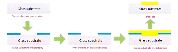
Figure 1 Glass substrate processing process diagram
a) Glass sheet material preparation
1. Ultrasonic cleaning with acetone and ethanol once, and rinsing with deionized water
2. Sulfuric acid: hydrogen peroxide cleaning 5min
3. Rinse with deionized water
b) Glass lithography
1. Glass lithography, adhesive thickness ≥2 microns
2. Hard film: 120℃, 15min
c) Solid corrosion of glass sheets to form anchor points
BHF corrosion, working temperature is 45℃, corrosion depth is 100nm
SiO2+6HF=H2SiOF6
d) Glass sheet metallization
1. Sputtering: Ti/Pu/Au
2. Thickness: 50nm/50nm/100nm
e) Strip glass to form metal wiring and pad
1. Ultrasonic cleaning with acetone and ethanol
2. Clean with deionized water
The process flow chart of SOI silicon structure processing is shown in Figure 2:
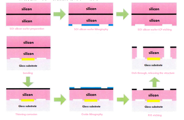
Figure 2 SOI silicon structure processing process flow chart
1. The size of the SOI wafer is 4 inches, the thickness of the structural layer is 70 microns, the thickness of the oxide layer is 3 microns, and the thickness of the substrate is 500 microns.
2. Ultrasonic cleaning with acetone and ethanol once each, rinsing with deionized water;
3. Sulfuric acid: hydrogen peroxide cleaning min;
4. Rinse with deionized water;
a) Silicon structure lithography
Wafer lithography (no numbered surface), adhesive thickness ≥2 microns
b) Silicon structure dry etching
1. ICP etching silicon
2. Etching depth 35 microns
c) Bonding
1. Silicon and glass substrate bonding
2. Voltage: 600V; Temperature: 300℃; Pressure: 300mbar
d) Corrosion
1. Corrosive liquid: 40%KOH temperature: 80℃
2. Corrosion until the oxide layer stops
e) oxide layer lithography
Oxidation layer lithography, adhesive thickness ≥2 microns, back alignment
f) Etching
1. RIE etching oxide layer, etching depth of 500nm (about 10min)
2. Remove photoresist
g) ICP etching through, release the structure, etching depth of about 55 microns
Although SOI technology with many advantages is the mainstream of MEMS gyroscope machining technology at present, there are still many shortcomings and machining errors in SOI processing technology, which is easy to cause the deterioration of gyro performance.
Among them, the key processes that affect the accuracy of image transfer include lithography and ICP etching. ICP etching will produce lateral overetching (deterministic process error), and random process error due to wafer flatness, warping degree, bending degree, photoresist exposure non-uniformity and so on. These process problems can cause structural errors such as uneven spacing of the comb teeth, uneven spacing between the side walls of the beam and the test mass block, uneven width of the beam and centroid deviation.
During RIE etching process, reactive ions will accumulate on the surface of silica due to Lag effect. When the number of reactive ions reaches saturation, that is, when the electric equilibrium state is reached on the surface of silicon dioxide, the reactive ions that continue to reach the surface of silicon dioxide are deflected by electrostatic force and move to the bottom sides of the trough, forming a root cut. For a single gyro, the root tangent will cause the gyro's sensitive structure centroid and resonant frequency to deviate. For the gyros processed on the same batch of wafers, the resonant frequency of each gyro will be greatly different, which will affect the consistency of the gyro performance parameters. In addition, the mass loss in the thinning process and the bonding residual stress in the bonding process will affect the structural characteristic parameters of MEMS gyroscope.
Conclusion
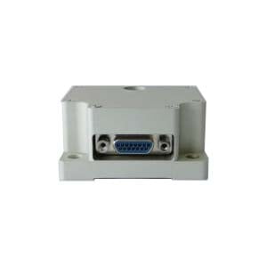
This paper introduces the processing technology and flow of MEMS gyroscope. Ericco is a manufacturer of MEMS gyroscopes, and you can focus on the two MEMS gyroscopes at the navigation level - ER-MG2-50/100 and ER-MG2-300/400, which are the north finding gyroscopes and navigation gyroscopes. ER-MG2-50/100 has bias instability of 0.01 to 0.02°/hr, while ER-MG2-300/400 has zero bias instability of 0.03 to 0.05°/hr.
If you want to know more about MEMS gyroscope, please contact us.
More Technical Questions
1.Integrated method of three-axis MEMS gyroscope
2.Development history of MEMS gyroscope
3.Impact resistance technology of MEMS gyroscope
4.Research on driving mode of MEMS gyroscope
5.Analysis of drive loop noise of MEMS gyroscope
6.Comparative analysis of integrated modes of three-axis MEMS gyroscope
Products in Article