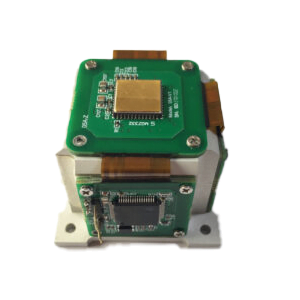
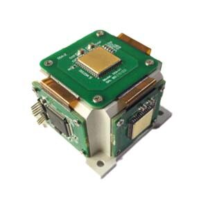
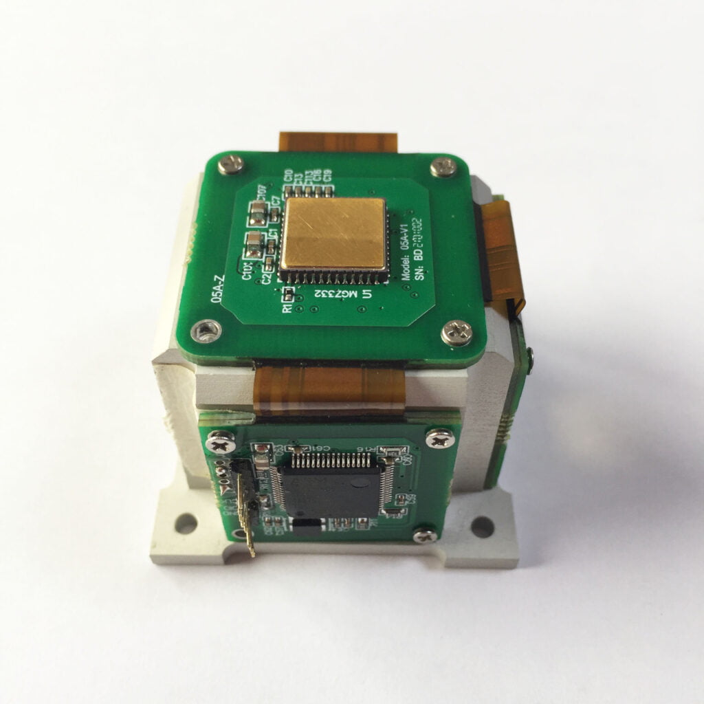
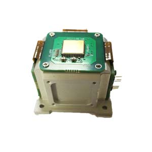
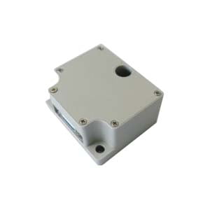
is an inertial measurement device composed of a three-axis accelerometer, a three-axis gyroscope, and a three-axis magnetic sensor. It is mainly used to measure the angular rate, acceleration, and magnetic heading of the aircraft's three degrees of freedom. The navigation-grade MEMS IMU independently developed by ERICCO can independently seek north. It adopts MEMS design and system integration methods. This product has the advantages of light weight, small size, low cost, and high reliability, and has been widely used in military and civilian fields.
The measurement accuracy of the inertial measurement unit is not only related to the detection accuracy of the inertial measurement component itself, but also to the processing technology and installation accuracy. Therefore, the research on the calibration and error compensation of the inertial measurement unit is of great significance.
The calibration methods of the IMU mainly include the traditional multi-position and angular rate calibration method based on the turntable and the on-site multi-position calibration method. Based on the position calibration method, a gyro calibration method that eliminates the north misalignment is given. The traditional calibration method is based on a high-precision turntable, and the calibration process is very complicated. On-site calibration can not only reduce the workload, but also effectively improve the calibration accuracy. Another calibration method is to combine the traditional static multi-position and rate calibration method and propose a 6-position calibration method based on a dual-axis rotating mechanism. This method is more convenient to solve the scaling factor and installation error, but it has a few steps when solving the constant drift. More cumbersome.
Next, the error sources of the IMU unit will be analyzed. An improved calibration method based on accelerometer and gyroscope is proposed. To understand this improved calibration method, we need to first understand the error model and calibration method of the inertial measurement unit. It will be further introduced from the accelerometer and gyroscope.
1.Inertial measurement unit error model
As shown in Figure 1, OXnYnZn is the orthogonal coordinate system, OXbYbZb is the coordinate system of the inertial measurement unit, and the three axes of the ideal gyroscope and accelerometer are respectively installed on three orthogonal surfaces to form a right-handed coordinate system. However, due to the working principles and structures of gyroscopes and accelerometers, as well as integrated manufacturing and installation, the input coordinate axes of the accelerometer and gyroscope in the inertial measurement unit cannot be orthogonal, and there are 6 orthogonal coordinate systems. Installation error angles θxy, θxz, θyx, θyz, θzx, θzy. The purpose of sensor calibration is to compensate for the calibration factor between the output value and the measured value, to compensate for the zero offset error, and to compensate for the installation coupling error caused by machining accuracy, assembly technology, etc.
 Figure 1. Installation error angle in non-normal coordinate system
1.1Gyro error model
The gyro output data is affected by the orthogonality of the coordinate system, installation accuracy and ambient temperature, which will cause changes in the gyro's zero bias, scale factor, installation error angle and noise. Therefore, the gyro's output model is. Therefore, the gyro's output model is One part is the measured angular velocity vector of the sensitive axis, and the other part is the real angular velocity vector, which will include a linear scale factor, a non-orthogonal matrix, a constant drift (zero bias), and a gyro noise error. Considering that it has a small impact on the calibration results, the noise is ignored. The impact of errors on calibration. Let K = I + Sω + Nω, then the formula can be expressed as:
 Among them, Kyx and Kzx are the coupling coefficients of the installation error angles θxy and θxz of the sensitive axis xg. Kxy and Kzy are the coupling coefficients of the installation error angles θyx and θyz of the sensitive axis yg. Kxz and Kyz are the coupling coefficients of the installation error angles θzx and θzy of the sensitive axis zg. Coupling coefficients, Kxx, Kyy, Kzz are the calibration coefficients of the sensitive axes xg, yg, zg, Dωx, Dωy, Dωz are the constant drift (zero bias) of the gyro sensitive axes xg, yg, zg.
1.2 Accelerometer error model
The accelerometer output data is affected by the orthogonality of the axis system in the coordinate system, installation accuracy and ambient temperature, which will cause changes in the accelerometer's zero bias, scale factor, installation error angle and noise, so the output model of the accelerometer is part of Measure the acceleration vector for the sensitive axis, and part of it is the true specific force vector, which will include nonlinear scaling factors, non-orthogonal matrix constant drift (zero bias), and gyro noise errors. Considering that it has a small impact on the calibration results, the noise is ignored The impact of errors on measurement results. Let C = I + Sa + Na, then the formula can be expressed as:
Among them, Cyx and Czx are the coupling coefficients of the installation error angles θxy and θxz of the sensitive axis xg. Cxy and Czy are the coupling coefficients of the installation error angles θyx and θyz of the sensitive axis yg. Cxz and Cyz are the coupling coefficients of the installation error angles θzx and θzy of the sensitive axis zg. Coupling coefficient, Cxx, Cyy, Czz are the calibration coefficients of the sensitive axes xg, yg, zg, Dax, Day, Daz are the constant drift (zero bias) of the accelerometer's sensitive axes xg, yg, zg.
2.Calibration of inertial measurement unit
2.1 Gyro calibration method
The scale factor and installation error of the gyroscope can be calibrated by the multi-position method. In order to minimize the calibration state, make the sensitive axis of the gyroscope point east or west during initial calibration, then the component of the earth's rotation rate in this axis is zero. Based on this principle, 4 states are selected from 24 states for gyro calibration. Rotate the inertial measurement unit to four different positions as shown in the figure below, record the output data of the three axial gyroscopes in sequence, and calibrate the zero bias, scale factor and installation error of the gyroscope.

2.2 Accelerometer calibration method
In its natural state, the accelerometer is not affected by any external force or angular velocity input except the acceleration of gravity and the rotation of the earth. The accelerometer calibration adopts the static multi-position calibration method. The IMU is rotated to 6 different positions as shown in the figure below, and the three-axis accelerometer output data output at each position is recorded in turn, and the zero bias and scale of the accelerometer are calibrated. factors and installation errors.

This article proposes a calibration method for low-cost inertial measurement unit zero bias, scale factor and installation error angle, which simplifies the calibration process and improves calibration efficiency. The calibration method was applied to the inertial measurement unit, which met the expected test requirements and verified the correctness and effectiveness of the compensation method. A scale factor temperature model and a zero-bias temperature model can be established to further improve the accuracy of calibration. The ER-MIMU-01 and ER-MIMU02 independently developed by our company (ERICCO) are calibrated using the above calibration method, which effectively improves the accuracy of the product. If you want to learn about and purchase IMU, please contact our technical staff.
More Technical Questions
1.IMU working principle & Tactical grade IMU product recommendations
2.Choosing an IMU: FOG IMUs vs MEMS IMUs
3.Application of IMU in the Field of Drones
5.What is the Difference Between IMU and AHRS?
Products in Article