The IMU algorithm refers to the inertial navigation system algorithm, which is used to estimate the speed and direction of an object based on data collected by inertial sensors (gyros and accelerometers). To use the IMU (Inertial Measurement Unit) algorithm to calculate speed and direction, data from the accelerometer and gyroscope need to be combined. The following will explain in detail the calculation of objects and speeds from collected data and the IMU algorithm.
Data acquisition and speed and direction calculation stepsData collection
The IMU algorithm works based on data collected by gyroscopes and accelerometers. Gyroscopes can measure the rotation speed of an object in three axes, while accelerometers can measure the acceleration of an object in three axes. This data is used to calculate the object's attitude (pitch, yaw, and roll angles) and velocity.
- Attitude calculation: The IMU algorithm calculates the attitude of the object through gyroscope data. Use quaternions or Euler angles to represent the attitude, and calculate the rotation angle and rotation axis of the object through continuous-time quaternions or Euler angles. By comparing the poses of the current frame and the previous frame, the rotation speed and angular speed of the object in three-dimensional space can be calculated.
- Speed calculation:The IMU algorithm calculates the speed of an object through accelerometer data. Objects will be affected by gravity when they move, and the components of gravity acting in different directions can be expressed as g. Therefore, the gravity component can be calculated from the acceleration measured by the accelerometer, and then the velocity and displacement of the object can be obtained through integration. At the same time, since changes in the attitude of the object will produce changes in inertia, the angular velocity of the object can be obtained through gyroscope data, and the rotation angle and rotation axis of the object can be obtained through integration.
- Fusion algorithm: In order to improve the accuracy and stability of the IMU algorithm, a fusion algorithm can be used to fuse sensor data such as gyroscopes, accelerometers and magnetometers. The fusion algorithm can use algorithms such as Kalman filter, complementary filter or Madgwick filter. By fusing data from different sensors, more accurate speed and direction information can be obtained.
2.Data preprocessing:In order to get more accurate results, you may need to perform some preprocessing on the original data, such as filtering or denoising. This can be achieved with various digital filters such as Kalman filters.
3.Calculate the accelerometer offset: Due to the Earth's gravity, the accelerometer will read a constant offset even if the device is stationary. To eliminate this offset, the accelerometer's offset needs to be updated periodically.
4.Calculate the angular velocity deviation:Similarly, the gyroscope may also have an initial deviation due to various reasons (such as errors during startup). This deviation can be estimated by comparing rotation angles over time and updated periodically.
5.Calculate speed and direction: Once you have the bias-corrected acceleration and angular velocity data, you can use these data to calculate speed and direction. For velocity, this can be found by integrating angular velocity; for direction, it can be found by integrating acceleration (but this usually results in cumulative errors, so more sophisticated methods such as magnetometers or GPS assistance may be needed).
6.Compensate for the effects of the Earth’s rotation:The Earth's rotation also creates a small rotational moment on the device, which affects orientation calculations. To eliminate this effect, it may be necessary to use some method to track the speed of the Earth's rotation and take this into account when calculating the direction.
7.Integrate other sensor data: To improve accuracy, you can also consider integrating other sensor data, such as magnetometers or GPS. A magnetometer can provide a device's absolute orientation relative to the Earth's magnetic field, while GPS can provide a device's precise location and timestamp, which is particularly useful for long-distance navigation.
Brief description of IMU algorithm
The IMU (Inertial Measurement Unit) algorithm is a complex system used to calculate speed and direction by combining data from accelerometers and gyroscopes. And collect its data and add it to the algorithm to output the attitude angle and speed information of the device. The following is a more detailed IMU algorithm process. This part will explain the above content in more detail.
1.Data collection:
IMUs typically contain accelerometers and gyroscopes. Accelerometers measure acceleration, while gyroscopes measure angular velocity. Data acquisition is accomplished through a microcontroller or computer, which periodically reads and stores the IMU sensor measurements.
2.Data preprocessing:
Due to the existence of noise and outliers, data denoising and filtering are required. Commonly used filters include the Kalman filter in Figure 1 and the complementary filter in Figure 2, which can combine accelerometer and gyroscope data to provide more accurate results.

Figure1: Kalman filter
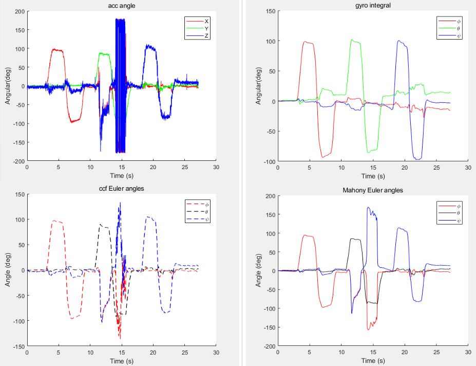
Figure2:complementary filter
3.Accelerometer deviation compensation:
The accelerometer is affected by the Earth's gravity when stationary, which causes a fixed bias in the measurement results. By comparing acceleration measurements over time, this bias can be estimated and compensated for.
4.Gyroscope deviation compensation:
The gyroscope may have an initial bias when it starts up, which affects the angular velocity it measures. This deviation can be estimated and compensated for by comparing angular velocity measurements over time.
5.Speed calculation:
Use integrated angular velocity to calculate the angle of rotation. By integrating the angular velocity twice, you get the velocity. This requires knowing the initial velocity and initial position.
6.Direction calculation:
Use integrated acceleration to calculate direction. But this approach can lead to cumulative errors because the Earth's rotation affects the device's orientation. To improve accuracy, corrections can be made in conjunction with data from other sensors such as magnetometers or GPS. A magnetometer can provide a device's absolute orientation relative to the Earth's magnetic field, while GPS can provide a device's precise location and timestamp.
7.Kalman filter application:
The Kalman filter (Figure 1) is an optimization algorithm used to combine data from multiple sensors to provide more accurate results. It uses mathematical models to predict sensor measurements and updates the predictions with new measurements. In IMU applications, the Kalman filter can be used to fuse accelerometer and gyroscope data to provide more accurate attitude angle (pitch, yaw and roll angle) and velocity information.
- Pitch angle θ (pitch): rotates around the X-axis.
- Yaw angle ψ (yaw): Angle of rotation around the Z-axis.
- Roll angle Φ (roll): The angle of rotation around the Y axis.

Attitude angle diagram
8.Output:
After the above steps, the IMU algorithm can output the attitude angle and speed information of the device. This information can be used in a variety of applications such as drone control, robot navigation, and motion tracking.
It should be noted that the implementation of the IMU algorithm involves complex mathematical operations and sensor fusion technology. In actual applications, further adjustments and optimizations may be required to adapt to different application scenarios and hardware devices.
Conclusion:
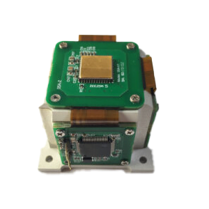
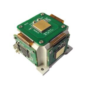
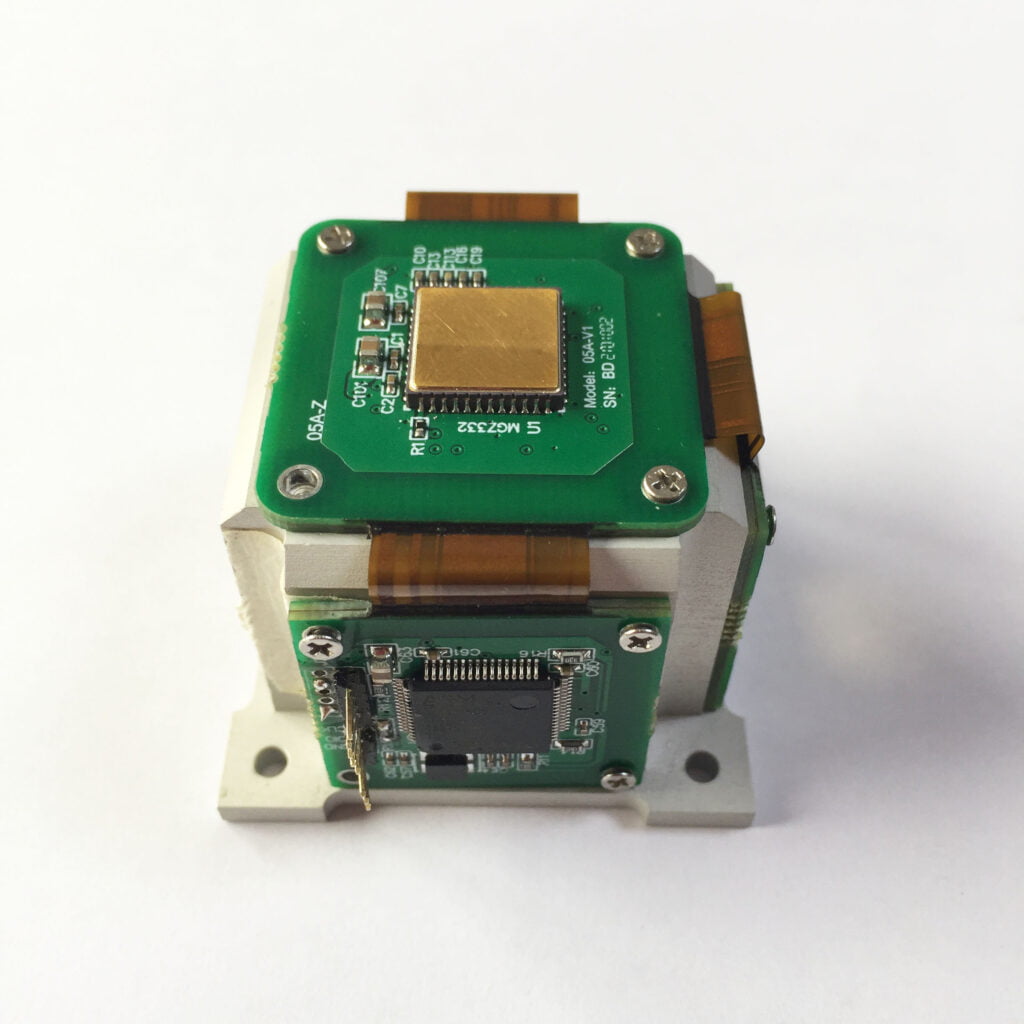
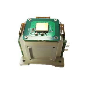
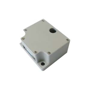
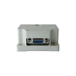
The above article briefly describes a detailed algorithm of IMU from data collection to speed and direction calculation. Through the processing and analysis of gyroscope and accelerometer data, the attitude, speed and direction information of the object can be obtained. In order to improve the accuracy and stability of the algorithm, a fusion algorithm can be used to fuse multiple sensor data. It is through this method that Ericco Inertial System. calculates the speed and direction of the IMU, which can more accurately measure the direction of the object. Your company is also constantly developing independently higher-precision IMUs. So far, ERICCO has developed Two types of IMU: MEMS IMU and FOG IMU. For example, the navigation-level ER-MIMU01 and ER-MIMU05 can independently seek north without relying on a magnetometer or GNSS. The accuracy of the gyroscope is also relatively high, the angular velocity random walk is less than 0.005, and the bias stability is less than 0.1°/h. Compared with other companies' products, it has great advantages and higher accuracy.
ERICCO's MEMS IMUs are divided into navigation-level and tactical-level. Compared with many top-ranking system companies, the biggest advantage of navigation-level IMUs is that they can independently seek north, which many large companies cannot achieve with MEMS IMUs. And they better reflect the inherent characteristics of MEMS IMU: small size, high performance, low cost, light weight and other characteristics. The most important thing is that these characteristics allow them to be produced in large quantities. This is relatively friendly to customers with high demand. If you want to know more about or purchase IMU products, please contact our technical staff.
More Technical Questions
1.Inertial Measurement Unit Error Calibration
2.IMU working principle & Tactical grade IMU product recommendations
3.Choosing an IMU: FOG IMUs vs MEMS IMUs
4.Application of IMU in UAV Flight Control System
5.Easy to Understand IMU Explanation
6.Application of IMU in the Field of Drones
Products in Article