

MEMS gyroscope is a new type of micro-inertial sensor, which can measure angular velocity with high precision, small volume and strong anti-interference, and is widely used in aerospace, platform drilling, automatic driving, mining, mapping and other fields. The application of the traditional gyroscope is restricted by its large volume, complex structure and high production cost. In the mid-1980s, MEMS based on the Coriolis effect developed rapidly, and its characteristics of small size, low cost, simple structure and low power consumption expanded the application field of gyro. This paper aims to introduce three levels of MEMS gyro classification and performance improvement methods.
Class classification of MEMS gyroscopes
Since the development of MEMS gyroscope is becoming mature, MEMS gyroscopes with different precision levels are produced to meet the requirements of different fields. According to the different accuracy of various technical indicators, MEMS gyroscopes are divided into three levels: consumer, tactical and navigation. The following table compares the accuracy levels of the three MEMS gyroscopes.
| Technical indicator | Consumer grade | Tactical grade | Navigation grade |
| Angular random walk/(°/√hr) | >0.5 | 0.50-0.05 | <0.001 |
| Bias instability/(°/hr) | 10-1000 | 0.10-10 | <0.01 |
| Scale factor nonlinearity/% | 0.1-1 | 0.01-0.10 | <0.001 |
| Bandwidth/Hz | >70 | 100 | 100 |
| Measuring range/(°/s) | 50-1000 | >500 | >400 |
Table 1 Comparison of technical indicators of three MEMS gyroscopes
1) Bias instability: when the input angular rate is 0, the dispersion of the gyroscope output around its bias.
2) Angle random walk: The total Angle increment accumulated by the gyroscope from time zero reflects the white noise characteristics in the angular rate signal.
3) Scaling factor nonlinearity: the ratio of the maximum deviation value of the output relative to the least square fitting line to the maximum output, reflecting the degree of deviation between the gyroscope output and the fitting line.
4) Measuring range: the maximum positive and negative input angular rate detected by the gyroscope, indicating the measuring range of the gyroscope.
5) Bandwidth: The gyroscope can accurately measure the frequency range of the input angular velocity, the greater the bandwidth, the better the dynamic response of the gyroscope.
According to the technical indicators of the different levels of MEMS gyroscopes shown in the table above, we introduce two actual MEMS gyroscopes to learn the navigation level and the tactical level in more depth.
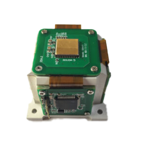
ER-MG2-200 is a high performance navigation-grade MEMS gyroscope with a range of 200°/s, bias instability of 0.02°/hr, and an angular velocity random walk of 0.005°/√hr. ER-MG2-200, as a newly launched navigation-grade MEMS gyro, is mainly used for north finding and ground navigation. Compared with other north finding gyroscopes, it can better meet the needs of various industries by expanding the measurement range while maintaining the same accuracy level.
ER-MG-067 is a high-performance tactical grade MEMS gyro with a range of 400°/s, bias instability of 0.3°/hr, and angular velocity random walk of 0.125°/√hr. Compared with the navigation grade MEMS gyro, the ER-MG-067 has a wider measurement range, but other accuracy levels are slightly lower, and MEMS gyro users can choose their own MEMS gyro type according to their own industry needs.
MEMS gyroscope performance improvement method
1. Harmonic oscillator layer
1.1 Miniaturization
MEMS gyroscopes are widely used in aerospace and autonomous driving fields. In order to improve the performance of the above systems, it is necessary to increase the compactness and redundancy of the sensors in the system, so the miniaturization of MEMS resonators is an irresistible trend. For high-performance resonators such as microhemispheres, it enables high-precision full Angle/force balance operations, but its three-dimensional geometry limits its further application, but this provides opportunities for new integration and packaging strategies. On the other hand, because the planar structure is more conducive to MEMS processing, in-plane harmonic oscillators such as tuning forks and disk types are more likely to break through the NEMS process. Recently Buffoli et al. proposed a NEMS tuning fork gyroscope with a 250 nm NEMS layer for piezoresistive sensing.
1.2 Structure Optimization
For gyro operating in various modes, its performance is closely related to the performance of the harmonic oscillator itself. The high requirement of harmonic oscillator makes the structure of harmonic oscillator more complex. Traditional MEMS design methods rely on the trial-and-error approach of the designer's experience (" build and break "), which is time-consuming and expensive. In recent years, with the rise of artificial intelligence technology, various intelligent optimization algorithms are expected to replace traditional optimization algorithms to improve the design efficiency of MEMS gyroscope. For example, based on intelligent optimization algorithms such as particle swarm optimization and genetic algorithm, high symmetric harmonic oscillator with low frequency difference and high quality factor can be manufactured to improve the bias stability of all-angle and amplitude modulation gyros. At the same time, the bandwidth of Lissajou FM gyro can be increased by deliberately enlarging the frequency difference.
2. Hardware circuit layer
2.1 Integration
Miniaturization and low power consumption are the development trends of MEMS gyroscopes, especially for open-loop and LFM gyroscopes with simple control circuits. Integrated circuits allow for circuit component specific optimization and can achieve trade-offs between power consumption, size, cost, and performance. Therefore, the application of ASIC circuits will further promote the commercialization of MEMS gyroscopes. In recent years, several integrated commercial open-loop and LFM gyroscopes have been reported, with power consumption below 40 μw and dimensions approaching 1 mm2. In addition, integrated high performance force balance gyros have been reported, with a size of 4.4 mm×4.5 mm and a power consumption of 50 μW.
2.2 Innovation of driving mechanism
The traditional MEMS gyroscope realizes the drive and displacement detection of harmonic oscillator by means of capacitors. For the driving mechanism, the driving force and vibration displacement need to be compromised by the pull-in effect, and the capacitive transducer may also bring nonlinearity, which will affect the performance of the gyroscope. Piezoelectric drives would be a potential alternative. Piezoelectric materials allow for increased displacement without capacitive nonlinear effects, which can help improve the resolution of LFM and open-loop gyros, or reduce the 4θ harmonics of all-angle gyros.
3. Software algorithm level
The upgrading of harmonic oscillator and hardware circuit can increase the precision limit of MEMS gyro, and the addition of software algorithm can make MEMS gyro fully realize its performance potential. Therefore, it is necessary to study the error modeling and compensation of MEMS gyro in various modes. For the traditional amplitude modulation gyro, its error compensation method has been relatively mature, but most of the existing compensation schemes only target at one kind of error. Therefore, a reasonable error compensation process can be designed based on the existing methods to eliminate multiple error sources in the gyro. For example, we should first consider eliminating the orthogonal error and phase error to suppress the leakage of the orthogonal component, and then identify and compensate the coupling damping error through calibration.
For full-angle mode, the damping error caused by harmonic oscillator defects is the main error source, but there is a lack of effective damping control scheme. The recently proposed damping correction scheme based on thermal resistance effect is expected to be widely used to eliminate coupling damping errors. In addition, although many compensation algorithms greatly improve the performance of MEMS gyroscope, most of these methods are offline and lack real-time performance. Therefore, it is necessary to develop the online compensation algorithm of full Angle gyro.
The research on error modeling and compensation technology of frequency modulation gyro is still in the initial stage. At present, a compensation scheme for coupling stiffness and coupling damping errors widely existing in gyros can be given priority. For example, coupling damping errors and quadrature errors of differential frequency modulated gyros can be eliminated by velocity feedback and orthogonal control loop suppression, and mode matching of QFM gyros can be realized by frequency difference of two axes as the characteristic quantity. In addition, the tilt Angle of the stiffness axis can be eliminated by electrostatic tuning, and the orthogonal error in the LFM gyro can be eliminated.
Conclusion
This paper introduces three grades of MEMS gyros and their technical indexes, and expounds the ways to improve their performance level. I hope that through this article you can understand the relevant knowledge of MEMS gyroscope, welcome to discuss with us.
More Technical Questions
1.Integrated method of three-axis MEMS gyroscope
2.Development history of MEMS gyroscope
3.MEMS gyroscope processing technology
4.Evolution of resonant structure of high precision MEMS gyroscope
5.MEMS Gyroscope: Sensitive Structure | Detection Circuit | Integrated Package
6.Comparison Of Technical Specifications Of Navigation Grade MEMS Gyroscope
Products in Article
 3-Axis North-Seeking MEMS Gyro
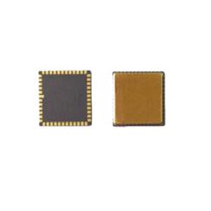
 High Precision Navigation MEMS Gyroscope
 2-Axis North-Seeking MEMS Gyro
 High Performance Navigation Grade MEMS Gyroscope