Application Techniques of Ericco MEMS Gyro
1.Application products:
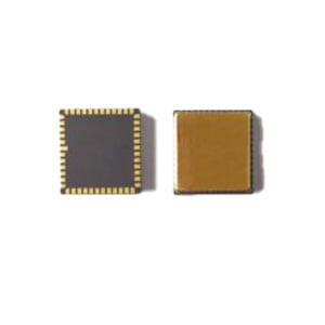
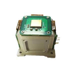
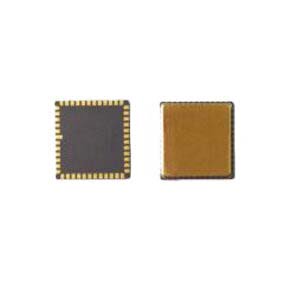
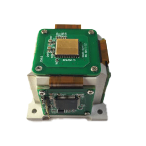
North seeking MEMS Gyro ER-MG2-100
Navigation grade MEMS Gyro ER-MG2-300/400
Tactic grade MEMS Gyro ER-MG-067
2.Instructions for switching the curing configuration to register control
The MEMS Gyro part of the control is open to the customer for customized tuning operations. If you need to modify this part of the setting, you need to switch the relevant module control from the solidified configuration to the register control state.

Figure 11 Configuration control mode switching
To write control parameters to the device module, the selection control bit of the corresponding module needs to be configured.
The read-back of control parameters of the corresponding module will also be distinguished according to the corresponding selection of control bits. Therefore, to modify the parameters of the functional module of the device, it is necessary to read back the current register value through SPI, modify the corresponding control, write, and then modify the selection control bit of module parameters.
3.Output signal bandwidth
The bandwidth of the MEMS Gyro output signal can be adjusted according to demand. The range of adjustment is 12.5Hz ~ 800Hz. Small output bandwidth helps to improve output noise but at the same time loses high frequency signal response and increases signal output latency. The specific setting needs to be adjusted according to the specific needs.
MEMS Gyro parameters are generally ex-factory cured. So if you need to adjust the output bandwidth, follow these steps.
3.1 Output Bandwidth Settings
1.Read the value of BW_CTRL (0x6D) and record it.
2.BW_CTRL (0x6D)[3:0]: BW_CRTL[3:0], set and modify the corresponding bit parameters. Be careful to keep the remaining bits
The bit value is unchanged. Write the new value to register BW_CTRL (0x6D)
3.Read and record the value of SYNC_BW_SEL (0x59).
4.SYNC_BW_SEL (0x59) [0]: BW_Sel, set to 0. Set Modifies the parameters of the corresponding bit. Pay attention to keep
Other bits remain the same. Write the new value to SYNC_BW_SEL (0x59)
3.2 Modify the output filter level
1.Read the value of BW_CTRL (0x6D) and record it.
2.BW_CTRL (0x6D)[5:4]: LPF_SEL[1:0], set and modify the corresponding bit parameters. Be careful to keep the remaining bits.
The bit value is unchanged. Write the new value to register BW_CTRL (0x6D)
3.Read and record the value of SYNC_BW_SEL (0x59).
4.SYNC_BW_SEL (0x59) [0]: BW_Sel, set to 0. Set Modifies the parameters of the corresponding bit. Pay attention to keep
Other bits remain the same. Write the new value to SYNC_BW_SEL (0x59)
Before changing the register related control bit, it is necessary to read the corresponding parameter register first, then modify the corresponding bit and write it, and then modify the register related control bit to switch to the register control state.
4.Data Update Rate
When internal synchronization is used to update data, the data update rate can be adjusted by modifying the data update rate register.
To change the data update rate, perform the following steps.
1.Read registers SYNC_BW_SEL (0x59), SYNC_CTRL (0x6A) and record.
2.SYNC_CTRL (0x6A) [6:4]: ODR_RATE, select the required data update rate. Setting Changes the corresponding bit.
The parameters. Leave the remaining bits unchanged.
3.SYNC_BW_SEL (0x59) [1]: Sync_ODR_Sel, set to 0, synchronization signal selection has register configuration. Set Modifies the parameters of the corresponding bit. Leave the remaining bits unchanged.
4.Write the new value to register SYNC_BW_SEL (0x59)
5.Output synchronization
MEMS Gyro supports the use of external synchronization signals to synchronize output. The synchronous signal requires a square wave with a 50% duty cycle. The input frequency is at least twice the required ODR.
By default, the INTERNAL synchronization clock is used to control the ODR. If you need to use external synchronous input, follow these steps.
1.Read registers SYNC_BW_SEL (0x59), SYNC_CTRL (0x6A), SYNC_DIV_H (0x6C) and SYNC_DIV_L (0x6B) and record.
2.SYNC_DIV_H (0x6C), SYNC_DIV_L (0x6B): SYNC_DIV: set the frequency division number of the input synchronization signal. Write the new value to registers SYNC_DIV_H (0x6C) and SYNC_DIV_L (0x6B);
3.SYNC_CTRL (0x6A) [2]: Sync_Polar, choose to use rising edge or falling edge as synchronization edge. Set Modifies the parameters of the corresponding bit. Leave the remaining bits unchanged.
4.SYNC_CTRL (0x6A) [1:0]: Sync_Mode [1:0], set to 1, select external sync signal input. Set Modifies the parameters of the corresponding bit. Leave the remaining bits unchanged.
5.Write the new value to register SYNC_CTRL (0x6A);
6.SYNC_BW_SEL (0x59) [1]: Sync_ODR_Sel, set to 0, synchronization signal selection is determined by register configuration. Set Modifies the parameters of the corresponding bit. Leave the remaining bits unchanged.
7.Write the new value to register SYNC_BW_SEL (0x59)
In setting, the fractional frequency of the input signal is 0, and then the ODR is generated after the input signal is divided into 2 frequencies as the output control signal. The specific calculation formula is as follows:
Before changing the register related control bit, it is necessary to read the corresponding parameter register first, then modify the corresponding bit and write it, and then modify the register related control bit to switch to the register control state.
More Technical Questions
1.Analysis of the main performance parameters of MEMS gyroscope
2.The Calibration Method of High Precision MEMS Gyro
3.MEMS gyroscope VS FOG: What’s the difference between them?
4.Feasibility Analysis of MEMS Gyro North Seeking
5.ER-MG2-100 (0.02°/h) High Precision MEMS Gyroscope
6.How do MEMS gyroscopes work?
Products in Article