Accelerometers are a typical type of inertial sensor, with wide and important applications in aviation, aerospace, navigation, weaponry, and civilian fields. However, the large size and high cost of traditional accelerometers limit their applications. With the development of Micro-Electro-Mechanical System (MEMS) technology, various MEMS accelerometers with small size, low power consumption, and wide application range have emerged.
In addition to the all-silicon structure, there are other measures to improve the overall temperature performance of MEMS accelerometers. Firstly, by effectively reducing the thermal stress transmitted to the sensitive structure through the stress elimination method proposed in the previous section, the overall temperature performance of the accelerometer is improved. Secondly, through the study of low-stress bonding parameters, low-stress stacking and packaging of MEMS accelerometers are achieved. Based on this, further improvement of the overall temperature performance of the accelerometer is achieved through third-order temperature compensation for accelerometer bias and scale factor.
1.Low-stress bonding process design
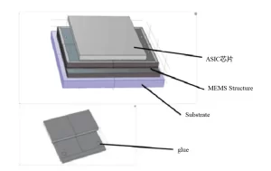
In order to reduce the packaging volume of MEMS accelerometers, this paper does not adopt the traditional method of packaging two chips flatly. Instead, it adopts a stacked packaging design with MEMS sensitive structures and Application Specific Integrated Circuit (ASIC) chips, as shown in Figure 1.
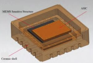
Fig.1 Schematic diagram of MEMS accelerometer stacking package
The MEMS chip is pasted onto the bottom plate of a ceramic tube casing using adhesive, while the ASIC chip is pasted on top of the MEMS chip. They are interconnected through wire bonding and connected to the packaging shell, forming the final accelerometer product after the metal cap is applied. In the stacked packaging design, both the bonding of the sensitive structure and the bonding of the ASIC introduce bonding stress, which is an important source of overall stress for MEMS accelerometers.
Bonding stress affects the overall temperature performance of accelerometer bias and scale factor. In order to minimize the packaging stress caused by the bonding adhesive of ASIC and MEMS sensitive structures, this paper establishes a finite element model of MEMS accelerometer stacked packaging, as shown in Figure 2. Through finite element analysis, the paper analyzes the influence of key process parameters such as bonding amount and bonding point size on the bonding stress of MEMS accelerometer chips or the change in detection capacitance. Understanding the relationship between the geometric parameters of the bonding layer and thermal stress will help in selecting reasonable bonding point size parameters, thereby reducing packaging thermal stress and improving the overall temperature performance of the accelerometer.
Firstly, the study investigates the thickness of the adhesive for bonding ASIC chips. The ASIC is bonded over its entire surface, with the adhesive thickness ranging from 10μm to 150μm. The maximum stress experienced by the simulated accelerometer sensitive structure is then analyzed. The simulation results are shown in Figure 3.
It can be observed from Figure 3 that the stress remains relatively constant once the adhesive thickness exceeds 25μm. In actual bonding processes, to ensure sufficient bonding strength, the adhesive thickness for ASIC bonding is not less than 25μm. Therefore, within a reliable bonding range, the parameter of ASIC adhesive thickness has a relatively large selection range, with insignificant effects on the thermal stress of the accelerometer sensitive structure.
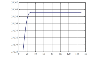
Fig.3 Effect curve of ASIC adhesive thickness on accelerometer-sensitive structural stress
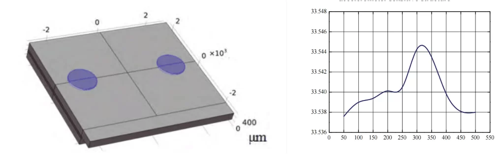
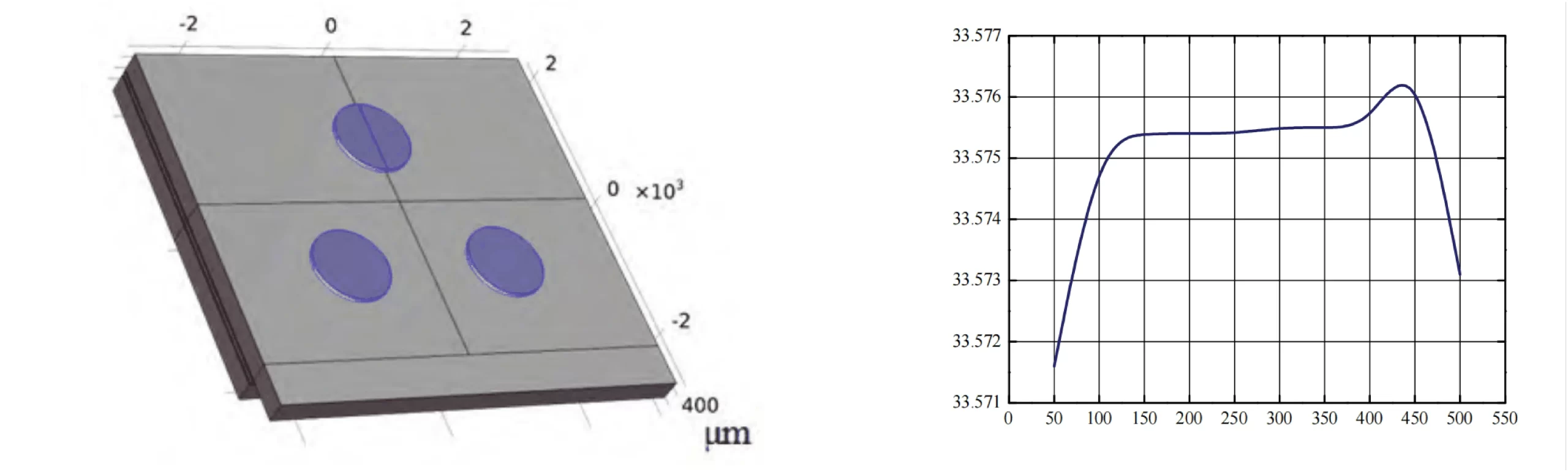
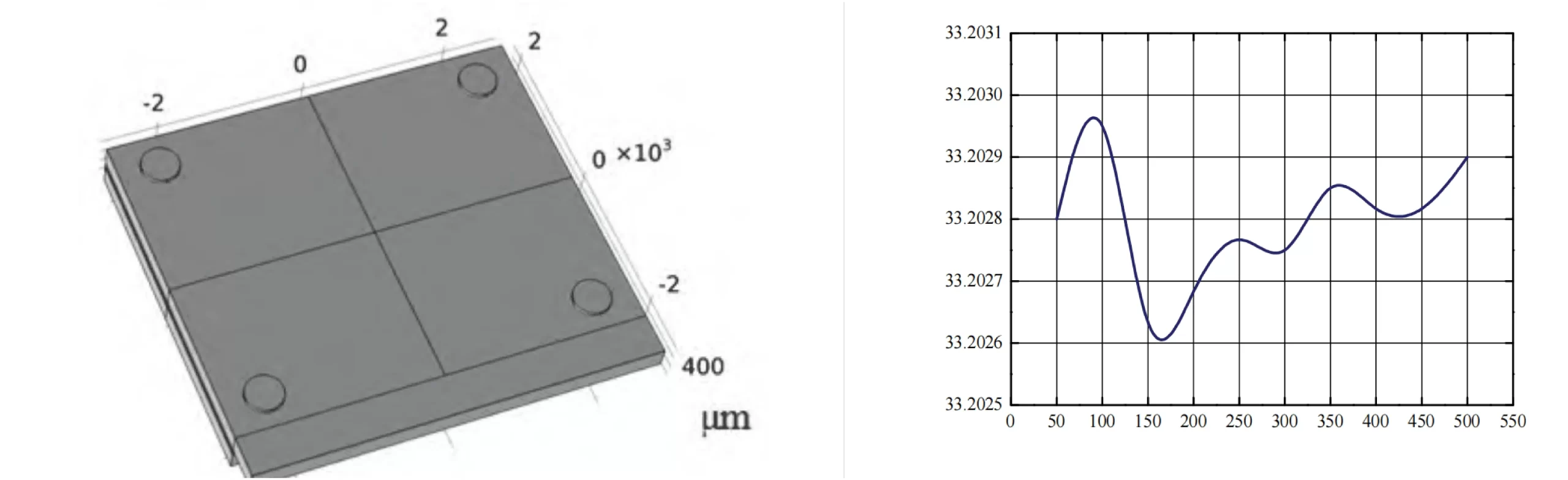
Next, the study investigates the effect of the distribution and size of adhesive points on the encapsulation stress of the accelerometer sensitive structure. Models of different point adhesive methods are established to determine the maximum stress on the accelerometer sensitive structure under the given adhesive form and adhesive point size through simulation analysis. The simulation results are illustrated in Figure 4.
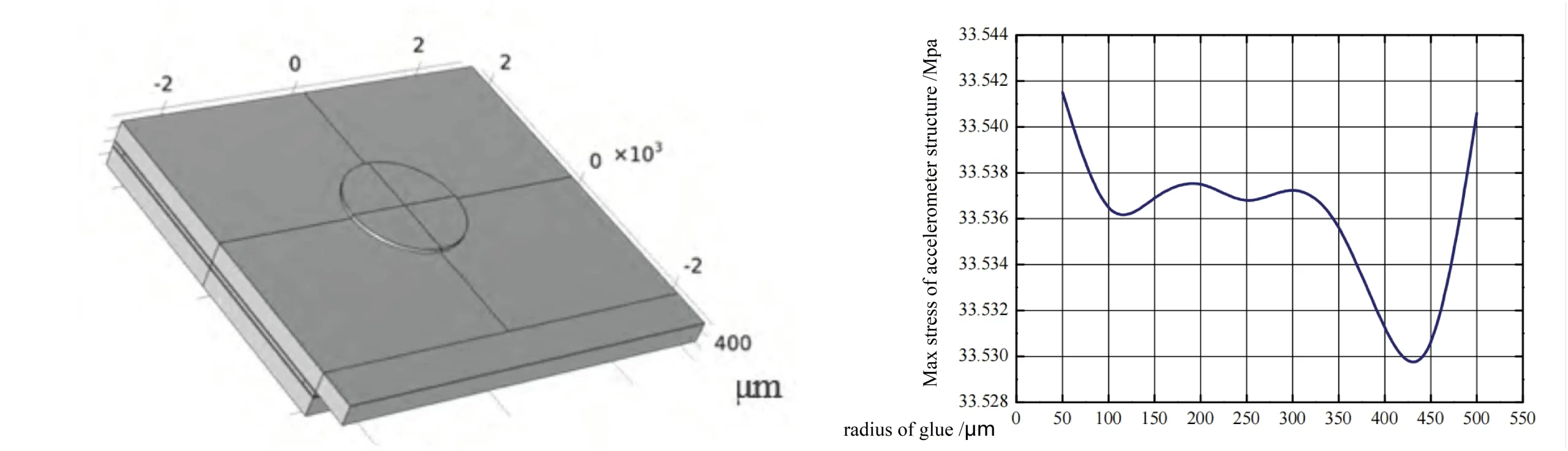
Comparing the maximum stress under four different point adhesive methods, it is observed that the maximum stress on the accelerometer structure is the lowest under the 4-point adhesive method, at around 33.202 MPa, while under the other three adhesive methods, the maximum stress on the accelerometer sensitive structure exceeds 33.5 MPa. Therefore, the 4-point adhesive method is chosen as the bonding method for the accelerometer sensitive structure. Additionally, from Figure 7, it can be seen that the structural stress is relatively low within the range of adhesive point radii from 138μm to 206μm. Hence, in setting the process parameters, choosing the adhesive radius for the sensitive structure within the range of 138μm to 206μm not only reduces the difficulty of adhesive process control but also keeps the stress introduced by bonding the accelerometer sensitive structure within a relatively low range.
Based on determining the 4-point adhesive bonding for the accelerometer sensitive structure and the adhesive point radius, to analyze the effect of adhesive thickness on the stress of the accelerometer sensitive structure, the stress of the accelerometer sensitive structure before bonding at room temperature is taken as the reference. The adhesive thickness parameter for the 4-point adhesive bonding is set from 10μm to 150μm. When the temperature rises from -40°C to 60°C, the maximum stress in the accelerometer sensitive structure is calculated. Figure 8 shows the curve of the effect of adhesive thickness on the stress of the accelerometer structure.
From Figure 8, it can be seen that the adhesive stress decreases with increasing adhesive layer thickness, and when the thickness exceeds 60μm, the reduction in adhesive thermal stress becomes smaller. Therefore, setting the adhesive thickness for the accelerometer sensitive structure to be above 60μm can keep the stress introduced by bonding the sensitive structure at a relatively low level.
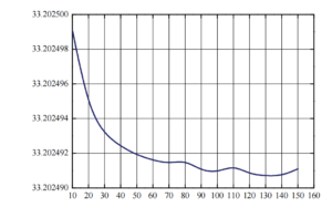
Fig.8 Bonding layer thickness vs. thermal stress
2.Temperature Compensation Design
In order to further enhance the overall temperature performance of the accelerometer, this paper, in addition to stress elimination design in structural design and low-stress bonding design in stacked packaging, also models and compensates for the accelerometer bias and scale factor separately. By modeling the accelerometer for temperature testing, the temperature sensor output, bias, and scale factor of the accelerometer at various temperature points are obtained. Then, polynomial fitting is performed separately for the bias, scale factor, and accelerometer temperature sensor output to obtain the bias fitting coefficients and scale factor fitting coefficients.
K0=p1·T3+p2·T2+p3T+p4
K0 is the accelerometer zero bias; p1, p2, p3, p4 are the third-order fitting coefficients of the zero bias; T is the accelerometer temperature sensor output
(K1/K1T)=q1·T3+q2·T2+q3·T+q4
K1 is the scaling factor of the accelerometer at normal temperature; K1T is the scaling factor of the accelerometer at each temperature point; q1, q2, q3, and q4 are the third-order fitting coefficients of the scaling factor,
The bias fitting coefficients and scale factor fitting coefficients are written into the accelerometer register to complete temperature compensation, with compensation range from -40°C to +60°C.
3.Conclusion
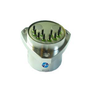
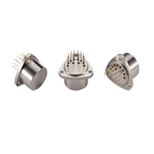
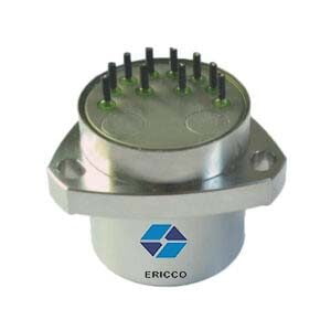
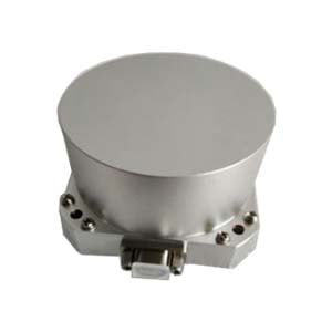
ER-MA-5 is a high-precision MEMS accelerometer, with a bias value of 5μg and a bias temperature coefficient of <10μg/°C. ER-MA-5 can be applied in multiple fields. It is an important tool for vibration measurement in various scenarios, including monitoring mechanical equipment, assessing the structural integrity of bridges and dams, and conducting safety tests. Its applications also extend to inertial guidance systems, aiding in precise navigation and overload measurement. The accelerometer is also used in integrated navigation systems to provide comprehensive positioning solutions.
More Technical Questions
1. Dynamic Attitude Measurement of Directional Drilling Tools Based on Q-Flex Accelerometer
2. Temperature Compensation Method for Q-Flex Accelerometers
3. Driving Automotive Evolution: MEMS Accelerometers
4. Factors Affecting the Stability of Q-Flex Accelerometers
5. Structure Design of High Precision Quartz Flexible Accelerometer
6. Methods to Maintain the Long-Term Performance of Quartz Flexure Accelerometers
Products In Article