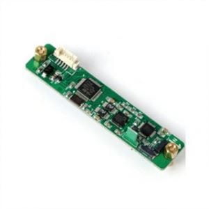
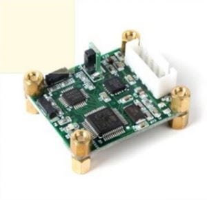
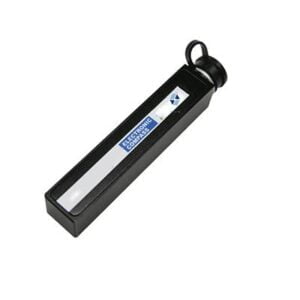
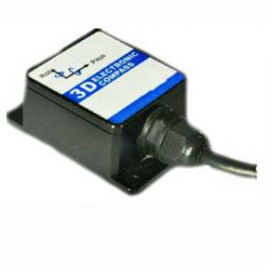
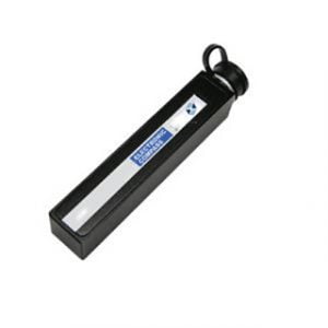
Electronic compass (also known as digital compass), is through the measurement of the Earth's magnetic field to complete the course calculation, often as a GPS signal or network is not effective supplement. Based on its advantages of small size, low energy consumption, high precision and miniaturization, it is widely used in the field of magnetic heading measurement such as UAV, Marine and automobile. However, in use, the electronic compass also has its own inherent defects: easy to be affected by external magnetic field interference and error, which is the main reason for affecting its measurement accuracy and restricting its application, so it is very necessary to study the method of compensating the measurement error of the electronic compass.
At present, there are many methods to compensate measurement error. For example, the compensation coefficient method is mainly aimed at the dynamic interference during measurement, while the static interference compensation effect is little, and the application range is small. Another example is the adaptive compensation method, which requires the system to achieve high compensation accuracy in the case of linear or low-speed movement, if the system rotates faster, the measurement accuracy will be greatly affected, so the more demanding application scenario makes this method not extensive. At present, if only a single error compensation model is used to compensate the compass error, it can not meet the requirements of the measuring system. In this paper, an error compensation algorithm based on ellipse hypothesis is proposed, which integrates the principle of least squares. The algorithm can realize effective compensation for the measuring error of the electronic compass, and has the characteristics of moderate calculation and wide application.
1.Error analysis of magnetic heading system
When the digital compass is installed in the carrier for magnetic heading measurement, its measurement error is caused by a variety of factors, which can be roughly divided into two categories: one is caused by the system's own structure, materials, assembly and other reasons, including compass, installation error, manufacturing error; The other is attitude signal error, although it does not belong to the heading measurement system itself, but it is involved in the calculation of heading parameters, will also cause measurement error. Because the compass error is the most difficult to control and has the greatest influence on the course accuracy, this paper mainly analyzes the compass error. The compass difference is mainly composed of the horizontal component of the hard iron magnetic field and the horizontal component of the soft iron magnetic field of the carrier. A large number of experimental studies show that the error caused by the hard ferromagnetic field on the moving carrier is a periodic error, which can be expressed by formula (1), and its rule is approximately sinusoidal curve; The error caused by the soft iron magnetic field can be expressed by formula (2), and the law changes with the change of the environmental magnetic field.

Where ϕi is the measurement of the heading Angle, and A, B, C, D, and E are error coefficients. Through the error analysis of the compass above, we can see that the total compass of the electronic compass should be the algebraic sum of the above errors. Therefore, combine formulas (1) and (2) to find the total difference ∆ϕ
![]()
2.Error compensation by least square method
Least Squares (LS) can be used to find the best function match of data by minimizing the sum of squares of errors. It is easy to obtain unknown data and minimize the sum of squares of errors between it and the actual data. The least squares method can also be used for curve fitting and is often used for data optimization.
The least square method can optimize the data fitting in the sense of minimum square variance. It is a mathematical optimization method that can compensate the error caused by the magnetic field interference of the external environment. Under normal circumstances, the measurement error presents a certain periodicity, a more suitable fitting method can be used trigonometric function method, based on the mathematical model of Fourier function, and then corrected according to the heading parameters provided by the standard compass. The following is a brief introduction to the basic principles of least squares.
When a correspondence between two variables y and x needs to be determined based on observations, assuming that they are linear, y at time t can be expressed as:

Where H1,H2,... Hn is n unknown parameters to be determined, x1 (t), x2(t),... xt(t) is a known deterministic function, such as the sine and cosine function of t. Let's say at time t1,t2... tn makes m measurements of y and x, hoping that the variables y and x1 (t), x2(t),... xt(t) to estimate their values. Then formula (4) can be expressed in matrix form: Y =X*H
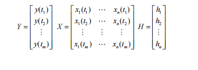
Using the least squares method, the least squares estimates of the error coefficients A, B, C, D and E shown in formula (3) are obtained from the known azimuth Angle measurement ϕi and azimuth Angle error ∆ϕ. The specific calculation steps are as follows: ① The eight-position error measurement method is adopted. Taking into account the number of samples, the amount of data calculation and the measurement accuracy, eight points with the same Angle interval within the range of heading Angle 360, such as 0, 45, 90, 135, 180, 225, 270 and 315, were taken to conduct heading error test, and 8 sets of data were obtained. ② The error coefficients A, B, C, D and E are obtained according to the principle of least squares. Through the previous analysis, when the error coefficients A, B, C, D and E are calculated by the least square method, the actual course of the carrier after error correction can be calculated by the calculation formula, and the specific research and analysis will not be done here.
3.Summary
Ericco company specializes in navigation products, in addition to the least method of error compensation, there are elliptic false method of error compensation and other compensation methods. In the research and development process of electronic compass, it has gradually mature technology and consolidated theoretical foundation. In addition to the continuous optimization of north finding accuracy, there are tilt compensation and other functions, if you are interested in our products, welcome to learn more about our low-cost 2D digital compass ER-EC-225, and 40° tilt compensation - 3D digital compass ER-EC-345 and so on, you can contact our professional and technical staff at any time.
More Technical Questions
1.Electronic compass dynamic heading error correction
2.Soft Magnetic Error Compensation Method of Electronic Compass
3.Electronic Compass Hard Magnetic Error Compensation
4.Application of Gyroscope in Electronic Compass
5.Principle of digital compass
6.What Is The Difference Between Gyro Error and Compass Error in Navigation?
Products in Article
