Navigation accuracy is crucial across various sectors, including aviation, maritime, automotive, and even personal navigation. The integration of Global Navigation Satellite Systems (GNSS) and Inertial Navigation Systems (INS) has significantly contributed to improving navigation accuracy, robustness, and reliability. In recent years, advancements in GNSS INS integration techniques have propelled navigation systems to new heights, offering enhanced performance even in challenging environments where GNSS signals may be obstructed or degraded.
- Background of GNSS INS Integration Development
Nowadays the global satellite navigation systems (GNSS) play a fundamental role in many areas as civil aviation, maritime and land navigation or geomatics, owing to the ability to provide worldwide, tridimensional, all weather position, velocity and time synchronization. A drawback of GNSS in general is the necessity to have a good light-of-sight visibility to the satellites. Signal-degraded environments as urban areas are critical locations for satellite navigation; buildings block many of the signals, thus reducing satellite availability and weakening observation geometry, with the extreme case being solution unavailability. Buildings can also reflect the signals causing multipath phenomenon, introducing large measurement errors.
For these reasons, standalone GNSS is not adequate to guarantee a continuous and accurate navigation in urban environment.In these scenarios GNSS system must be augmented with other sensors to allow an accurate and continuous navigation. The recent enhancement of GLONASS satellite system suggests the combined use with GPS in order to increase the satellite availability, especially in places with lack of GPS signals; also GLONASS measurements are affected by blocking and multipath problems in urban areas. Inertial sensors are well suited for integration with GNSS systems owing to their complementary features.
Unlike GNSS systems, the inertial navigation systems (INS) are self-contained and their performance is not degraded in environment as urban canyons, being independent of external electro-magnetic signals.
Furthermore, INS exhibit superior short-term accuracy and can provide data continuously at high rates (several hundred Hz), compared to GNSS receivers which typically update position and velocity at lower frequencies (1 to 20 Hz). Additionally, INS can provide attitude information. However, the main drawback of INS is the degradation of performance over time, necessitating regular updates to bound errors to acceptable levels. GNSS measurements can be used for this purpose. A common configuration involves a GPS receiver combined with a high-end INS capable of providing navigation solutions during GPS gaps. Nonetheless, the use of high-end INS is generally restricted to applications requiring high accuracy navigation and georeferencing due to their cost and size.
Recent advancements in Micro-Electro-Mechanical Systems (MEMS) technology, particularly in MEMS gyroscope, have facilitated the development of low-cost inertial sensors characterized by small size and light weight. These advancements present an attractive option for commercial applications such as pedestrian and vehicular navigation.
2. Strategies of GNSS INS Integration
Several approaches can be used to integrate GNSS and INS systems, differing by the “depth” of the interaction and for the shared information between the systems. The more common strategies are listed below:
- Uncoupled Integration
- Loosely Coupled Integration
- Tightly Coupled Integration
- Deep or Ultra-Tight Integration
In the Uncoupled approach, the systems work independently providing two distinct navigation solutions; usually GNSS one is considered more accurate and is adopted when available as system solution. Moreover GNSS solution is used to correct (or reset) the INS solution, but without estimating the causes of the sensor drift (as happens in the other integration approaches). In absence of GNSS data the system solution is entirely supplied by the inertial sensor, which tends to drift rapidly according to its grade. For this limitation the Uncoupled strategy is not commonly used.
The Loosely and Tightly Coupled strategies are more common integration techniques and will be illustrated following. In the Loosely Coupled approach the GNSS solution is merged with the inertial based information to obtain the final output of the integrated system, while in the Tightly approach the integration is “deeper”, because the GNSS raw measurements are directly combined with the INS information in a suitable filter.
2.1 Loose (Position Domain) Coupling
Fig. 2 shows a typical block diagram for a loosely coupled approach. Loosely coupled approaches require the least amount of GNSS knowledge by the navigation system designer. The designer need not understand the ephemeris computations, clock models, receiver specific implementation issues, or various other items discussed in the GNSS interface documentation. Various factors come into play related to the computation of the GNSS position and velocity measurements by the receiver. These factors are manufacturer dependent and may not be fully understandable or controllable by the user.
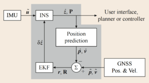
Position and velocity are not the basic measurements of a GNSS receiver. Instead, position and velocity can be computed by the receiver at any time when signals from at least four satellites are available. The accuracy of the position and velocity solutions depends on the number and geometry of the available satellites. This accuracy can change significantly over time.
Without an internal navigation filter, the GNSS receiver will not produce any position and velocity outputs at times when signals from fewer than four satellite vehicles are available. At these time instants, the information from the available satellites is lost. The internal filter is often preferred by GPS-only users of the receiver, but is a complication that can cause anomalous behavior in GNSS-aided INS implementations. For INS aiding, the receiver settings should eliminate its internal navigation filter.
2.2 Tight (Observable Domain) Coupling
Fig. 3 shows a typical block diagram for a tightly coupled approach. The tightly coupled approach requires more effort and knowledge on the part of the designer and more computation by the INS computer. The INS must implement the satellite ephemeris equations to compute the satellite position and velocity necessary for predicting the pseudorange, Doppler, and carrier-phase. The designer must also understand certain intricacies (e.g., clock models and interpretations of quality indicators) of the GNSS receiver with which they are working. The return on the invested design effort is the opportunity for improved performance. INS aiding is possible by whichever satellites are available, even when the number available is less than four. The accuracy of each satellite measurement can be independently and accurately characterized. In addition, validity decisions can be made on a per satellite basis, before they effect the navigation solution.
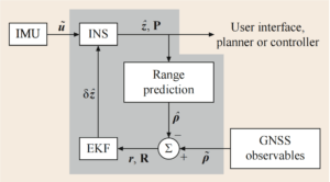
At present, most available GNSS receivers, if provided with differential correction signals, will utilize the corrections in its computed position, but will not account for the corrections in the pseudorange, Doppler, and carrier-phase measurements that are output. The designer must account for the differential corrections in the residual formation process.
3. Specific Implementation:GNSS INS Integration in Autonomous Vehicle
In the 21st century, the advancement of automatic driving has focused on three key elements: positioning, perception, and planning control. With the increasing complexity of driving environments, automatic positioning technology has evolved from GNSS to integrated GNSS/INS systems. Angrisano et al. (2010) highlighted the limitations of GNSS alone in achieving consistent positioning in urban areas and proposed various integrated GNSS/INS approaches. They introduced the Rauch Tung Striebel Smoothens (RTSS) algorithm in the same year to enhance the accuracy of Land-Vehicle Navigation (LVN) by addressing GPS signal loss and INS error accumulation during urban navigation.

In 2021, a semi-tight coupling mode combining multi GNSS PPP and Stereo Visual Inertial Navigation Systems (S-VINS) was introduced. This mode facilitated data exchange between the two systems, significantly enhancing vehicle positioning capabilities. Comparative data revealed that the 3D positioning accuracy of GPS, GPS+GLOANSS, GPS+, and GPS+GLOANSS+BDS systems was 49.0%, 40.3%, 45.6%, and 51.2%, respectively, surpassing the original solutions. Furthermore, the semi-tight coupling model of Multi-GNSS PPP/S-VINS improved 3D positioning accuracy by 41.8-60.6% compared to multi GNSS PPP/INS configurations.
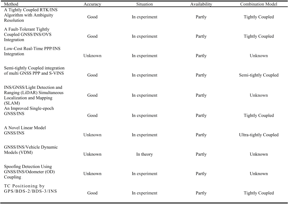
TABLE 1 demonstrates some cases of GNSS/INS integrated navigation. According to the indicators in the table, it can be seen that the positioning accuracy of the above-integrated navigation has been significantly improved compared with GNSS, and the positioning error is also reduced, which is of great significance for the realization of high-precision positioning of unmanned vehicles. These combinations are different modes, and the different coupling degrees would inevitably affect the accuracy. However, analyzing the table carefully reveals that all varieties have some usability flaws that need to be improved.
Synthesizing the above analysis, realizing the high-precision positioning of the automatic driving vehicle remains a complex problem. The application of GNSS/INS Integrated Navigation in automatic driving still needs to be investigated through continuous experiments in the future. At the same time, real-time fault detection of GNSS/INS integrated navigation is necessary to improve the stability of system operation and adapt to the rapid development of automatic driving. The second section introduces the general application of GNSS and GNSS/INS in automatic driving in recent twenty years.
4. Conclusion and Prospecting
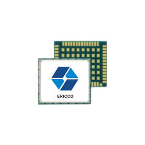
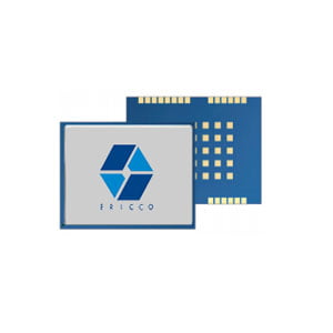
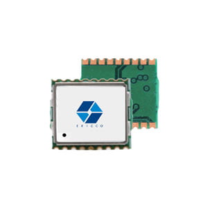
As technology advances, the cost of sensors and computation was rapidly decreasing, whereas the capabilities of both were rapidly increasing. One notable example is the ER-GNSS-M01, a high-precision positioning GNSS module. It comes equipped with a built-in 9-axis IMU (Inertial Measurement Unit), enabling onboard integrated navigation and providing an interface for inertial navigation data. This product can be seamlessly integrated with high-performance inertial navigation equipment to enhance the accuracy of integrated navigation systems. As a result, it finds widespread use in various applications such as handheld Geographic Information System (GIS) devices, unmanned aerial vehicles (UAVs), and autonomous driving systems.
In addition, the number of independent GNSS’s and their capabilities are rapidly increasing. GPS modernization is only one example of the increased number of signals and signal strength that is becoming available. These various factors taken together indicate a very bright future for the accuracy, integrity, and availability of navigation systems at cost points low enough for new and rapidly evolving commercial applications.
Finally, there are several opportunities for aiding by non-GNSS sources: feature aiding via RADAR, light detection and ranging (LIDAR), or vision; digital communications-based ranging by DTV, digital radio, or cell phone (signals of opportunity (SOO)). In addition, some of these alternative signals, such as cell phones, are becoming reliable sources for communication of real-time GNSS differential corrections.
At the same time, recreational, commercial, sporting, and military users have all had a small sample of the interesting new applications possible from reliable and accurate real-time navigation solutions. Some of these applications-for example, autonomous vehicles, safety-augmentation systems, or manned safety-of-life systems-require high levels of integrity with predictive indicators of certain accuracy specification violations. GNSS-aided inertial systems are the dominant technology with a bright future for such applications.
A current challenge for all existing approaches is the detection and mitigation of spoofing. This is one challenge that may be addressable by integration of information from various sources, including GNS, IMU, vision, radar, signals-of-opportunity, and soon.
I will appreciate it if you find this article help you a lot. For more information, please read the articles and products below.
More Technical Questions
1. Analysis of Spoofing Detection and Mitigation Techniques for GNSS
2. Precision Mapping in Mining Operations: The Role of GNSS Augmentation Technology
3. Positioning Performance Comparison of GNSS PPP
4. Performance Analysis of GNSS RTK Timing
5. Construction Surveying: Unleashing New Energy with the Help of GNSS
6. Application of GNSS-RTK Positioning Technology in ICV Testing
Products in Article