MEMS gyroscope is an inertial sensor which is manufactured by MEMS technology and measures angular rate based on Coriolis effect. Its application field is wide, the precision level is gradually improved, and it has the advantages of small size, light weight, low cost, good reliability and so on. In order to deeply introduce the principle and theoretical basis of MEMS gyroscope, this paper will analyze the Coriolis force and the mechanical characteristics of sensitive structures in detail.
The details of Coriolis force
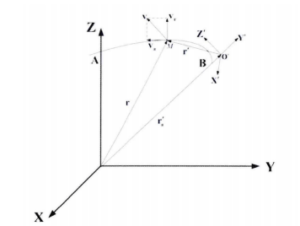
Figure 1 Correlation diagram between the inertial coordinate system and the rotating reference coordinate system in Coriolis effect
As shown in Figure 1, OXYZ is selected as the inertial coordinate system, and the coordinate system O’X’Y’Z’ rotating around the Z axis of the inertial coordinate system is the rotating reference coordinate system. Assume that the point M is a moving point in the coordinate system O’X’Y’Z’, and the instantaneous angular velocity of the rotating reference coordinate system is ω and the instantaneous angular acceleration is ℇ. From the addition law of vector space, the absolute velocity vector of point M can be obtained as:
va=vr+ve
Where va is the absolute velocity vector of point M, vr is the relative velocity vector of point M with respect to the rotating reference coordinate system O’X’Y’Z’, and ve is the implicated velocity vector.
Take the first derivative of both sides of the above formula with respect to the time variable at the same time, then the absolute acceleration vector of point M can be expressed as:
![]()
Where aa is the absolute acceleration.
Meanwhile, the implicated velocity ve and implicated acceleration ae of point M in the above formula can be expressed as:
ve=ω×r
ae=ℇ×r+ω×ve
Where r is the radial velocity vector of the rotating reference coordinate system with respect to the inertial coordinate system.
Find the derivative of the implicated velocity ve with respect to the time variable, and substitute the above formula into the obtained result, we can get:
![]()
Similarly, the derivative of the relative velocity vr of point M with respect to the time variable can be expressed as:
![]()
Where ar is the relative acceleration.
If the above formula is brought in at the same time, then the absolute acceleration aa of point M can be expressed as:
![]()
Also:
aCor=2ω×vr
Then the formula of absolute acceleration aa can be simplified as:
aa=ar+ae+aCor
According to the above formula, the aCor component that constitutes the absolute acceleration aa is the Coriolis acceleration. Coriolis acceleration was first theorized by French scientist Coriolis in 1835, and named after the acceleration, when the acceleration acts on the particle M, the force is Coriolis force, also referred to as Coriolis force.
From the above theoretical derivation process, it can be seen that when the implicated motion of a particle is a rotational motion, the implicated and relative motion of the particle are coupled to each other, resulting in the implicated acceleration and Coriolis acceleration in addition to the relative acceleration. The amplitude of the Coriolis acceleration is proportional to the cross product amplitude of the angular velocity of rotation and the relative velocity of the particle. Therefore, when the object is in a known or controlled relative velocity condition, the angular velocity ω of the rotating coordinate system can be obtained by measuring the magnitude of the Coriolis acceleration or Coriolis force on the measured object equipped with a rotating coordinate system. Moreover, since the Coriolis acceleration is the cross product of the angular velocity ω of the rotating coordinate system and the relative velocity vr of the rotating coordinate system, the vector direction of this acceleration is perpendicular to the plane determined by the rotational angular velocity and relative velocity of motion. Therefore, linear vibrating MEMS gyroscope based on Coriolis effect are designed in such a way that the direction of the detection mode, which measures Coriolis acceleration, is perpendicular to the direction of the driving mode, which provides controlled relative motion.
Mechanical properties of MEMS gyroscope sensitive structures
From the theoretical description of the Coriolis effect in the previous section, the magnitude of the angular rate can be obtained by measuring the magnitude of the Coriolis acceleration of a moving object. As a kind of angular rate sensor, gyro usually generates Coriolis acceleration by detecting the rotation, vibration or surge of mass. Most MEMS gyros are vibrating angular rate gyros, whose main mechanical component is a two-degree-of-freedom vibrating structure. The vibration structure can vibrate in two directions in the same plane. Considering the difficulty of micromachining, MEMS gyroscope adopts simple planar rigid mass structure. MEMS vibrating gyro can be divided into two types: linear vibrating gyro and angular vibrating gyro according to the different modes of vibration mass movement. This paper mainly discusses linear vibrating gyro, but most of the conclusions given in this paper can also be applied to angular vibrating gyro. In general, the main components of MEMS line vibration gyro include: a detection mass block supported by an elastic support beam, an electrostatic drive module and a detection module. Among them, the electrostatic driving module is used to drive the detection mass block to vibrate, and the detection module is used to detect the displacement or speed of the mass block. According to the different detection mechanism, the detection module can be divided into capacitive, piezoelectric, piezoresistive and optical types. The mechanical structure of MEMS gyroscope can be equivalent to a two-degree-of-freedom mass-spring-damping system model.
The detection mass block in the gyro can move in the XOY plane. Because it is driven by the electrostatic driving module, it vibrates along the X axis, so the direction along the X axis is the driving direction, and the vibration mode along the X axis is the driving mode. The overall structure is affected by the angular rate around the Z axis, so that the mass block vibrates along the Y axis and generates Coriolis force. Then the Y axis direction is the detection direction, and the vibration mode along the Y axis is the detection mode.
Conclusion
This paper introduces the Coriolis force and sensitive structural mechanical properties of MEMS gyro. MEMS is a new type of technology, with the continuous optimization of its own structure calibration in recent years, constantly improve the level of accuracy, and continue to get involved in a wider range of applications, MEMS gyroscopes have been enough to compete with other types of gyroscopes. MEMS gyro is not only active in the consumer field, it has gone deep into the high-precision field such as the tactical level and navigation level. In order to develop and produce MEMS gyroscopes with excellent performance, Ericco uses advanced equipment to test and calibrate MEMS gyroscopes, mainly for tactical and navigation level fields. For example, the excellent ER-MG2-50/100 is a navigation-grade north finding MEMS gyroscope developed specifically for ground navigation, while the ER-MG2-300/400 is a navigational MEMS gyroscope developed specifically for air and sea navigation. There are also tactical gyroscopes ER-MG-067 and ER-MG-068, which are slightly less accurate than the navigation level, but still have excellent performance.
I hope that through this article you can understand the knowledge of MEMS gyroscope, if you want to learn more related knowledge, you can click on the relevant articles and links below to continue to understand.
More Technical Questions
1.Bias Temperature Compensation Analysis of MEMS Gyroscope
2.System error and calibration of MEMS gyroscope
3.Sensitive structure analysis of MEMS gyroscope
4.The impact of turntable error on MEMS gyroscope calibration
5.Comparative analysis of typical high performance MEMS gyroscopes
6.How does MEMS gyroscope work in harsh high temperature environment?
Products in Article