MEMS accelerometers are based on microelectronics and micro-nano manufacturing processes, and are widely used in unmanned driving, industrial monitoring and other fields.Due to their significant characteristics such as low volume, weight and power consumption, low cost, high integration and resistance to harsh environment. Its core technology mainly includes four aspects: sensitive structure, processing technology, application-specific integrated circuit and package integration. In recent years, with the continuous optimization of sensitive structure design, the continuous progress of micro-processing capability, and the continuous growth of application-specific integrated circuit design technology, the accuracy of accelerometers has been rapidly improved, and it has gradually met the high-precision requirements of inertial measurement, precision guidance and other fields. At present, integrated packaging technology has become a key link that restricts MEMS accelerometers to the stage of engineering availability.
1.MEMS accelerometer package features
MEMS accelerometers undergo two processes before practical engineering applications: the packaging of sensitive structures and application-specific integrated circuits and the welding of the meter head to the PCB circuit board. These two processes will inevitably introduce external parasitic stress, mainly including:①In the packaging process, due to the mismatch of the thermal expansion coefficient of the accelerometer packaging material, the sensitive structure will produce thermal mismatch stress in the process of temperature change; ②When the accelerometer head is welded to the circuit board, the external parasitic stress generated during the welding process and when the circuit board is subjected to external temperature or mechanical loads. As a mechanical sensor, the silicon micro-capacitive accelerometer is extremely sensitive to stress, and the stress of the above different levels will eventually be transferred to the sensitive structure, which will have a great impact on the internal capacitance, resulting in a large change in the total temperature output curve before and after welding, and then affect the total temperature zero bias stability of the whole table. Therefore, it is very important to study how to reduce packaging stress and isolate external stress to improve the total temperature performance of MEMS acceleration sensor.
2.Encapsulation mechanism
2.1 Encapsulation Model
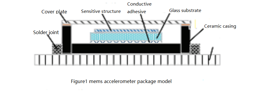
The MEMS accelerometer head is composed of a variety of materials and a multi-channel assembly process. The sensitive structure chip is composed of the silicon sensitive structure on the upper layer and the glass base on the lower layer, and the silicon and glass are connected together by electrostatic bonding method. The sensitive structure chip is fixed in the ceramic shell through the chip adhesive, and the cover plate is welded by sealing welding process after nitrogen is filled into the cavity of the ceramic shell. The sensitive structure with the package is called the meter head. The accelerometer meter head is welded on the PCB board to realize the electrical connection between the circuit and the sensitive structure chip. The packaging model is shown in Figure 1.
2.2 Research on packaging stress mechanism
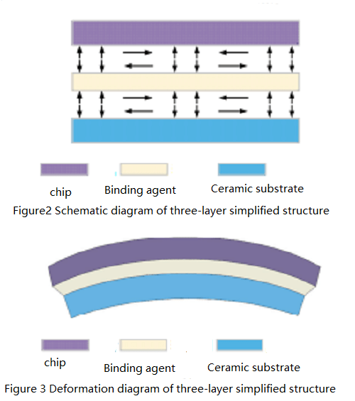
In the accelerometer packaging model, the packaging stress mainly comes from the curing process of the adhesive. Common binders begin to cross-link curing at high temperatures, when the interior of the package structure is in a stress-free state. When the curing is completed, the temperature is cooled to room temperature. Due to the different thermal expansion coefficient of each layer material in the package structure, the contraction displacement of each layer structure is different, resulting in the bending deformation of each layer structure. This is only to consider the "chip - adhesive - substrate" three-layer simplified structure, the actual MEMS accelerometer packaging model is more complex than the simplified structure, especially after the meter head is welded to the PCB, the multi-level stress and strain will be more complicated with the temperature disturbance.
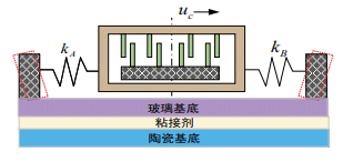
According to Figure 2, the upper and lower surfaces of the adhesive produce internal shear stress and normal stripping stress with the contact surface of the chip and adhesive (the lower surface of the MEMS chip) and the contact surface of the substrate and adhesive (the upper surface of the ceramic substrate) respectively. Shear stress is the main source of deformation, which transfers residual stress throughout the structure. As can be seen from Figure 3, the thermal expansion coefficient of the adhesive is greater than that of glass and silicon, resulting in the overall warping deformation of the lower surface of the MEMS chip and the upper surface of the ceramic substrate. From the perspective of thermal mismatch, the stress in the PCB board or ceramic substrate will be transferred to the chip structure through the adhesive, and the adhesive can absorb part of the stress through its own deformation during the stress transfer process, and ultimately reduce the stress transferred to the MEMS structure layer.
3.The effect of packaging stress on mems accelerometers
The mems accelerometer is based on Newton's second law, and its spring-mass block equivalent model is shown in Figure 4.
When the temperature changes, due to the thermal mismatch between the materials, the spring beam on both sides presents a state of extrusion or tension. Ideally, the thermal deformation of the elastic beam on both sides is the same, which can cancel each other out. However, due to the existence of machining errors, the stiffness of the spring beam on both sides kA≠kB, and the above stress at different levels will eventually be transferred to the MEMS inertial sensor sensitive structure, resulting in the overall displacement of the mass block, which will lead to changes in capacitance (voltage). As shown in Figure 5,when the temperature changes, this effect will become difficult to compensate, which is directly reflected in the zero drift and hysteresis phenomenon of silicon microcapacitive accelerometers.
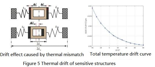
According to the output definition of the accelerometer, the zero temperature drift coefficient BTD of the micro-accelerometer can be calculated as follows :BTD= ΔP0 /ΔT = kA-kB /m (αeq La-αsi Lm) = kA-kB /m, where, BTD is the ratio of zero change ΔP0 caused by temperature change ΔT to temperature change ΔT. kA represents the stiffness of the spring beam on the left side of the accelerometer; kB represents the stiffness of the spring beam on the right side of the accelerometer; m represents the effective mass of the mass block; La represents half of the anchor distance; Lm represents half the length of the mass block; αsi represents the thermal expansion coefficient of monocrystalline silicon. αeq represents the equivalent thermal expansion coefficient of the package model as a whole.
According to the above formula, the equivalent thermal expansion coefficient of the whole package model changes with temperature, leading to the existence of zero drift phenomenon. From the perspective of adhesive material and bonding mode, increasing the thickness of the adhesive and decreasing the shear modulus of the adhesive can reduce αBTD, and effectively improve the zero temperature drift phenomenon of the silicon micro-capacitive accelerometer.
4.Summary
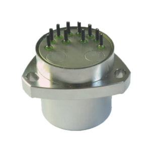
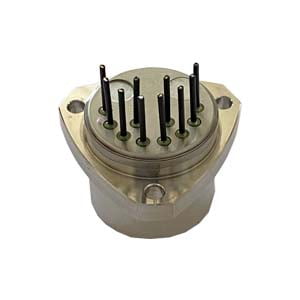
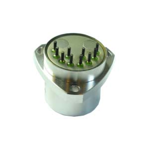
The above contents briefly introduce the packaging principle and influence of mems Accelerometer. High Accuracy MEMS Accelerometer ER-MA-5 can use this packaging technology in daily applications and also meet the partial stability (Allen variance) of 5 μg. With a monthly repeatability of 200μg and a measurement range of 20g, it is believed that the continuous optimization of packaging technology in the future will continue to reduce the errors that occur in applications.
More Technical Questions
1.Calibration Method of Accelerometer
2.How to Improve the Long-term Stability of the Quartz Accelerometer?
3.What Effect Does Temperature Have on Quartz Flexible Accelerometer?
4.What is Sensitivity and Measurement Range in Quartz Accelerometer?
5.What is the Effect of Temperature Coefficient on Quartz Accelerometer?
6.What are the Advantages and Disadvantages of Quartz Accelerometers?
Products in Article