- Background
Intelligent Urban Positioning (IUP) strives to attain precise and accurate object or individual positioning within urban environments through the utilization of advanced technologies and systems. The term encompasses the integration of various technologies to overcome challenges in densely populated and complex urban landscapes. Achieving reliable meters-level positioning in such areas proves challenging and cost-effective with a singular method. The solution lies in amalgamating multiple positioning techniques, and Intelligent Urban Positioning (IUP) aims to achieve this enhanced performance by combining three key ingredients:
- Multi-constellation GNSS;
- Detection of non-line-of-sight (NLOS) signal propagation;
- Three-dimensional mapping.
- Urban Positioning Challenges
The urban environment presents two major challenges to GNSS signal reception. Firstly, the buildings and other obstacles, such as buses, block the direct line-of-sight (LOS) to many of the satellites, effectively reducing the number in view. Consequently, a multi-constellation receiver is essential in order to reliably obtain sufficient direct-LOS signals to compute a position solution. At many urban locations, a full global deployment of all four GNSS constellations will be required for a high positionsolution availability.
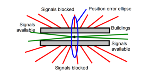
Due to the obstruction of signals from buildings across the street, only signals along the street remain, resulting in suboptimal geometry for position solutions. This leads to a significant increase in dilution of precision across the street compared to along the street, consequently causing lower accuracy in the cross-street direction, as depicted in Figure 1.
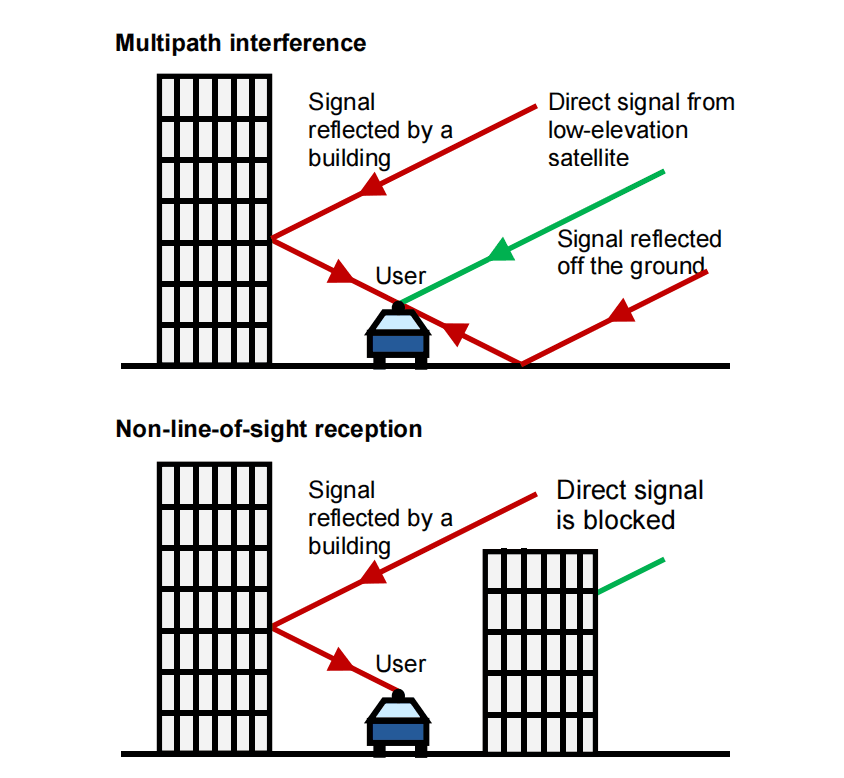
The second issue arises from the presence of numerous flat surfaces in urban environments, reflecting GNSS signals. Modern structures made of glass and metal exhibit strong reflective properties, and the reflective nature of water further amplifies this effect. Receiving signals reflected from these surfaces introduces considerable positioning errors attributed to Non-Line-of-Sight (NLOS) reception and multipath interference. Although commonly categorized as "multipath," it is crucial to recognize that these phenomena are distinct, generating distinct ranging errors, as illustrated in Figure 2.
3. 3D Mapping Integration
3.1 Advanced NLOS And Multipath Mitigation Using A 3D City Model
In scenarios where the user's position is precisely known, leveraging ray tracing with a 3D city model allows for the determination of Non-Line-of-Sight (NLOS) signal path delays, facilitating corrections to pseudo-ranges. When the user's position lacks the necessary accuracy but is sufficiently defined to identify reflecting surfaces reliably, a model can be established to correlate path delay with the user's position, enabling the utilization of NLOS signals for position determination.
In cases where position uncertainty introduces multiple potential reflecting surfaces for each NLOS signal, the task of NLOS correction becomes notably intricate. Ray tracing proves valuable in identifying path delays caused by reflected signals leading to multipath interference with direct signals. Determining maximum pseudo-range errors resulting from this interference involves considering the path delay and the receiver's response model. This information allows for the exclusion or appropriate down weighting of relevant signals in the position solution.
Theoretically, correcting multipath errors using a city model is feasible, but it demands the incorporation of relative amplitude, phase, surface reflectivity, and phase shift data in the model. This level of detail is necessary for achieving centimetric accuracy in determining the path delay. It's essential to note that tracing the path of a reflected signal is a significantly more complex challenge compared to discerning the blockage of a direct signal. The building boundary method, effective in reducing real-time processing load for direct signals, cannot be applied to this intricate task. Consequently, applications of 3D city models are prioritized in positioning.
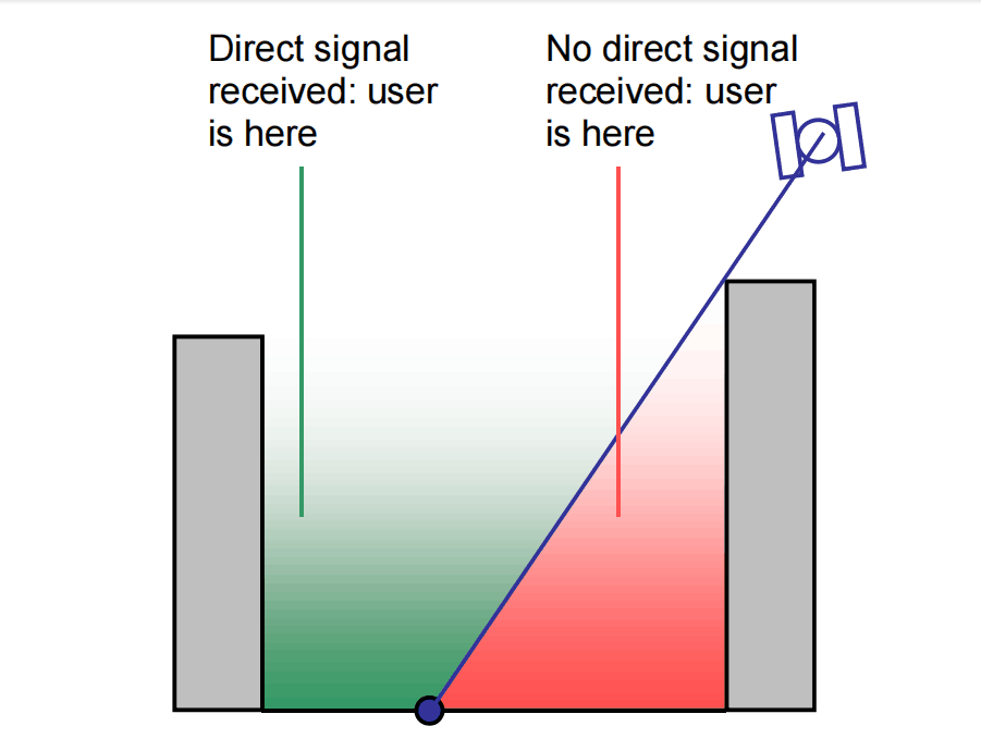
3.2 Shadow Matching
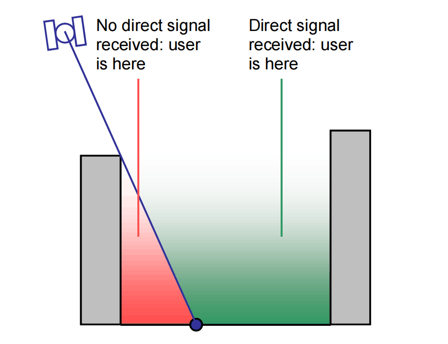
Shadow matching is a new positioning technique using GNSS and a 3D city model and is intended for use alongside conventional GNSS positioning. The basic principle is that positioning information may be inferred from which signals are receivable and which are not. Figure 3 illustrates the concept. If a satellite is visible in some parts of the street but not others, the user can be localised to one part of the street or the other depending on whether the signal is received. Repeating the process with another satellite, the position solution is refined further. This approach enables satellite signals that are not receivable to contribute to the position solution.
In current implementation of shadow matching, the building boundary method is used to predict satellite visibility over a grid of candidate positions. The grid extends to the uncertainty bounds of the initial position solution. Each candidate position is then scored according to how well the measured and predicted satellite visibility matches. This is an example of the pattern-matching positioning method, as opposed to the ranging method used in conventional GNSS positioning.
A shadow-matching position solution is currently obtained simply by taking the average of the positions of the highest-scoring candidate positions in the search grid. Further research will be conducted to identify a more optimal positioning algorithm.
Experimental testing of a basic algorithm in London using a survey-grade multi-constellation GNSS receiver has demonstrated that shadow matching can reliably determine which side of the street the user is on under conditions when conventional stand-alone GNSS positioning cannot. Thus, shadow matching provides an enhancement to conventional positioning in cases where the cross-street accuracy is poor due to the signal geometry.
In this basic algorithm, signals were assumed to be either received via a direct-LOS path or not received at all. However, in practice, NLOS and diffracted signals will also be received. If these are treated as direct-LOS performance will be degraded. The initial shadow matching testing did indeed produce signals that were observed but not predicted by the model at the correct location. In most cases, the shadow matching algorithm gave the correct solution in spite of this. However, to get the best performance out of shadow matching, direct-LOS, NLOS, and diffracted signals should be treated differently.
For conventional positioning, signals that may or may not be NLOS should generally be excluded if sufficient direct-LOS signals are available. By contrast, shadow matching makes use of all GNSS signals, including those that are not received at all. However, as a pattern-matching technique, shadow matching is inherently probabilistic. Consequently, a signal may be treated as having a certain probability of being NLOS and a certain probability of being directLOS.
4. Conclusion
This article primarily focuses on the advanced mitigation of Non-Line-of-Sight (NLOS) multipath using a 3D city model. It introduces a novel positioning technique called shadow matching, which involves pattern matching the observed GNSS signals with predictions derived from the 3D model.
It's important to note that much of the Intelligent Urban Positioning (IUP) discussed here is still in the conceptual stage. The determination of the eventual combination of hardware, mapping, and algorithms, along with the tuning of those algorithms, will require extensive further research.
Notably, emphasis is placed on the ER-GNSS-M10 module, featuring embedded multi-frequency point anti-jamming technology. This module enhances the multi-mode and multi-frequency Real-Time Kinematics (RTK) engine solution, leading to substantial improvements in RTK initialization speed, measurement accuracy, and reliability—particularly in challenging environments like dense city blocks and areas with abundant tree cover. As a result, the module is a viable option for positioning applications in densely populated urban areas.
I will appreciate it if you find this article helps you a lot. For more information, please read the products below. Always feel free to contact us:
Email: info@ericcointernational.com
More Technical Questions
1. Positioning Performance Comparison of GNSS PPP
2. Precision Mapping in Mining Operations: The Role of GNSS Augmentation Technology
3. Application of GNSS-RTK Positioning Technology in ICV Testing
4. Integration of GNSS Modules in Aviation: Precision Navigation for Unmanned Aerial Vehicles (UAVs)
5. Decoding Navigation Technology: GNSS Boards vs. GNSS Modules – Unveiling the Distinctions
6. Distinctions Between GNSS Receivers and Antennas
Products in Article